CabMasterPro User Guide
This tutorial discusses the concept of custom shapes which take a machining shape and create a 3D shape from it.
In this example there is just one section, and one component with machining.
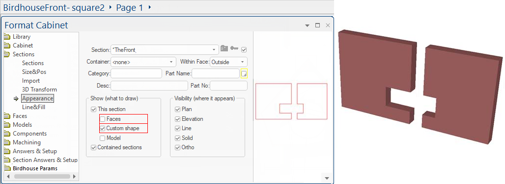
To make the custom shape, you need to first go to the section appearance tab and make "This section" show its "Custom Shape", as above.
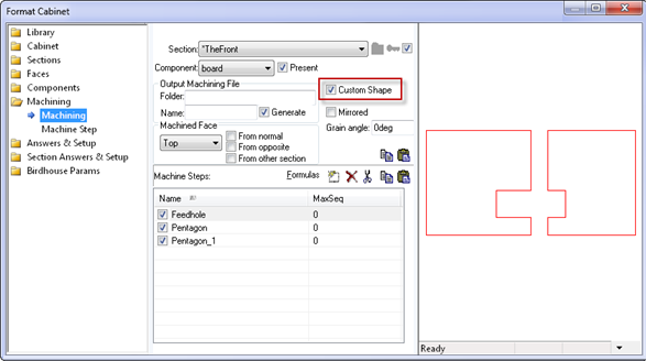
Then down in the machine steps for this section, in any component(s), you need to create one or more custom shape polys that it can use. In this example we have one component only and it has its "Custom Shape" checkbox set, like this:
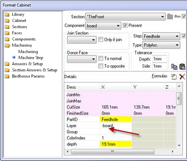
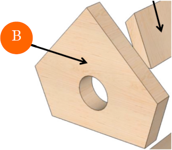
All poly machine steps are now able to contribute to the custom shape. In this case there are three but one (the step called "Feedhole") is a notch, because it has a minus sign in front of its layer name, which is "-board"
This causes it to cut the notch out of the other two polys, giving the shape you can see in the plan, 3D and other views.
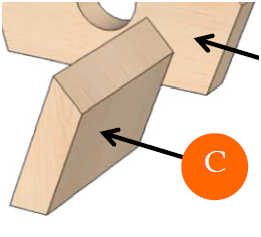
Combining both of these concepts would allow us to create "tapered" holes which get narrower (or wider) as you go deeper into the part, as shown below.
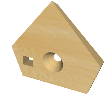
We can also have multiple internal contours.
As mentioned before, custom shapes use machining, specifically poly-type steps, to create the top and bottom surfaces of a custom shape, which are simply offset by the depth of the container section and joined together at the appropriate vertices to create a 3D solid object.
How do we specify different top and bottom shapes?
We now allow notches to be completely internal to a poly and create a hole - there is no longer any need for the '-board- notch to intersect the edges of the outer shape.
We also have the capability to create a vertically contoured shape by providing multiple polys at different depths.
The following example (BirdhouseFront-stackthoughts2.qid) illustrates both of these...
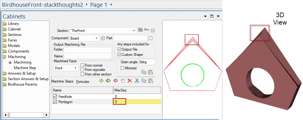
Note that again there is only one section and one component. Note also the "Custom Shape" checkbox for the machine steps of this component.
In this case, there are two machinesteps in the list, but the second one is a sequence (MaxSeq=5), and that lets us provide 5 contours for the pentagon shape at different depths.
Looking at the "Pentagon" step, we can click on the sequence spinner and see the five depths and also see the poly changing as the top vertex changes its y height:
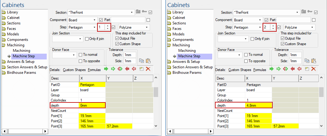 |
...etc... The depths go 0mm, 4.8mm, 9.5mm, 14.3mm and finally 19.1mm, the full depth:
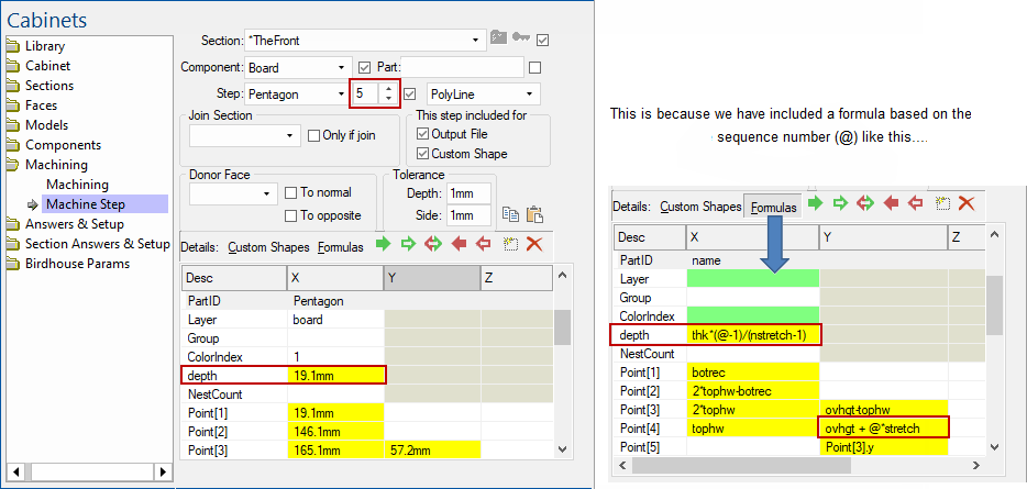
Here, thk is the full depth (19.1mm) and there are nstretch (=5) steps in the sequence.
The formula multiplies thk by (@-1)/4, which is 0, 1/4, 1/2, 3/4, 1 so we get different depths for each poly.
Zero depth is the top poly, and 19.1mm is the full depth, or bottom poly.
To make the pentagon change steps at different depths, the example adds a variable @ * stretch to the Point[4].y which is the y-value of the top vertex of the pentagon.
If you turn the model side-on you can see this changing height in the solid shape.
Of course in a real world example, you could pull these heights and offsets from a more complicated formula or perhaps from a lookup table. It would be quite feasible to have the middleware with a combo to select a lookup table by name (with friendly names) and then lookup values to use for maxseq and also the depth and offset for each member of the sequence. The offset could be used to grow or shrink a border-arch machine step, making a fancy edge contour on a door, or whatever.
The other step is the hole. In this example it is made up as a polyarc with four quarter circles. It is in the layer "-border" so the minus sign makes it a hole.
We don't have to use a machine step sequence with formulas in order to get contoured shapes at different depths. We can explicitly make a group of steps that each start with the same prefix followed by the separator "__" double underscore. In this example, the prefix is "Hole__" so these steps group together to form a contoured shape for the hole.
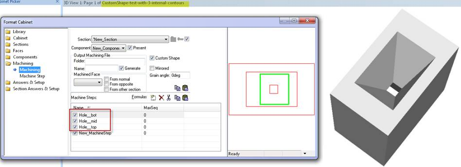
The fourth step just creates the overall outer rectangle. All three holes are in the same layer as the outer rectangle, but have a minus sign in front of the layer name to make them into holes.
It is ok to use a mixture of machine step sequences and individual steps (same prefix plus double underscore). These steps will be combined to form one big group with the shape being specified at as many depth levels as you provide.
There is no need for different groups of steps to have the same number of depths. For example, you could have an outer poly specified with 5 depths and several holes at different places and there is no need for these holes to have the same number of steps. So one hole could be specified with 8 depths and another could be straight through with no shape, and so on.