CabMasterPro User Guide
When doing machining, particularly when donor-acceptor situations are being handled, it is important to understand face coordinates. Typically machining is specified imagining a 2D surface and defining the routing and drilling that takes place on that surface. The machining is defined in "face coordinates". This means that the xy-plane is the face itself, and z is the perpendicular direction to that face.
In order to fully specify face coordinates for any face, you need to know where the origin is on the face (x=0 and y=0, z=0 is always on the face). You should also know the "up" or positive z direction, also called the "normal" direction.
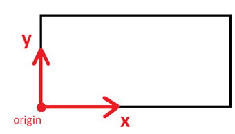
In simple situations, the face coordinates are the "obvious" ones. For example, looking down in plan view at the top face of a section, we see a rectangle, and the origin is the bottom left corner:
See also Vertex Position Properties
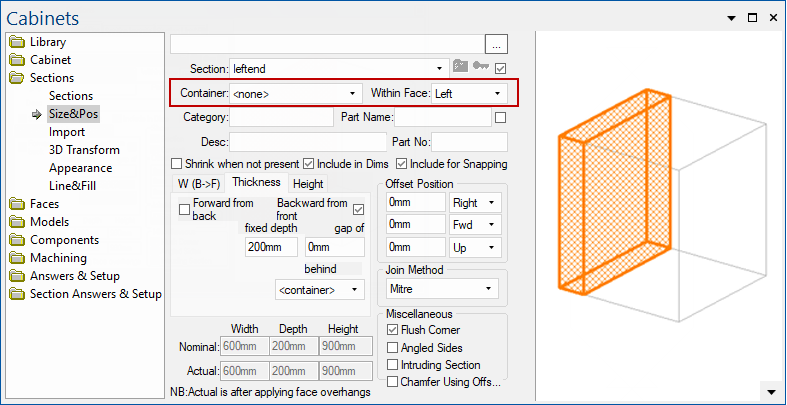
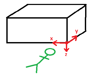
When we are looking at vertical faces, the situation is like this. Here we are looking at a section which is at the left end of the nominal box, and we have shaded its right face.
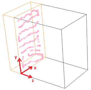
Looking at the right face, the bottom left corner is as shown with x- y- and z-axes marked.
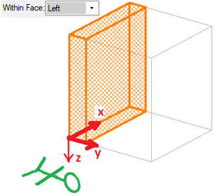
The situation is similar if this section is not in the nominal box, but is constructed by putting it in the left face of the nominal box. We do that like this, (container= means use the nominal cabinet box for a container):
In this case, the shaded face of our earlier diagram is actually the "back face" of this section because we are looking at the left face of the nominal box as a container. However, once we are on this back face, it still has its origin at the lower left corner with x y and z-axes as shown above.
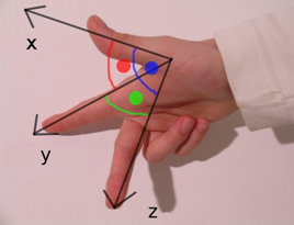
With bottom faces, defining the origin as the "bottom left corner when looking at the face" leaves some ambiguity. To look at the face we have to lie under the cabinet and look up. Now it depends whether we crawl under head first or feet first. In our coordinate system definitions, we have adopted the "AutoCad arbitrary axis algorithm" which resolves this ambiguity, and effectively determines that we must crawl under head first.
So for the bottom face of a simple section like the one above, we crawl under head first and look upwards at the face, observing the corner marked in red above as our "bottom left" corner, which is therefore the face origin.
The direction that we crawl is always from the front of the section towards the back. This means that if the section is "within a face" we have to crawl under from that face. So for example, when this section is within the left face of the nominal box, the origin corner is now different:
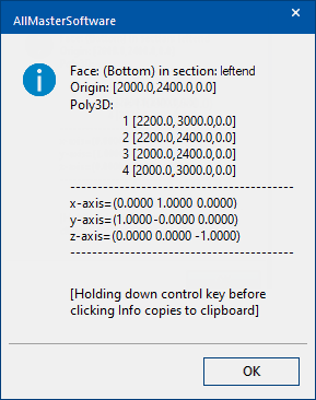
We can use the face "Info" button to check the origin, normal and vertices of a face in world coordinates:
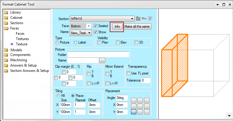
Notice we have selected the bottom face in the dropdown above the Info button, and in this example, the section is within the left face of the nominal box still. So pressing the info button gives this information. You can verify the axis directions are the same as those in the previous section.