

Here are some typical tools and a worked example of their use.
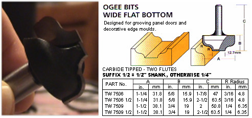
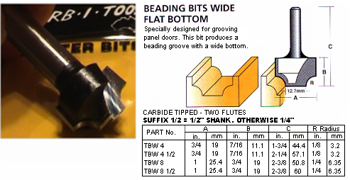
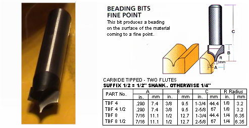
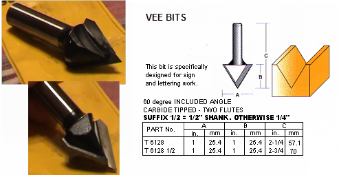
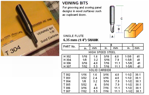
The following is an example of using the above tools.

The beading cutters come as a matched pair - the wide point and fine point cutters have the same circular shape profile.
The reason for this is so that the internal corners created can be sharper. In order to align these cutters correctly, look carefully at the specs supplied by the tool maker. You will see that the flat base is 1mm wide for the fine point cutter, and 12.7mm wide for the wide point cutter. So the radiuses of the bases are half this, i.e. 0.5mm and 6.35mm. For the bottom of the arcs to line up perfectly, the cutters must therefore be offset by 6.35mm i.e. 0.5mm = 5.85mm with respect to each other, and must cut at the same depth.
In summary, to line up these two cutters perfectly, use online engraving in EzyNest, and ensure that the wide point cutter is 5.85mm inside the toolpath for the fine point cutter.
After setting up these two beading cutters, the next step is to finish squaring the corners with the Vee cutter. EzyNest ramps at the corners to do this squaring if you use a 3D engrave and specify internal offsetting. To match the cuts correctly, you want to make the bottom tip of the V touch the inside corner at the top of the arc for the beading cutter, like this:

For a 3D engrave you must tell EzyNest/EnRoute the position of the outside of the cut, not the centre line as before.
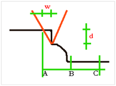
The diagram on the right shows what the three cuts look like when combined, with the tip of the V exactly at the top of the beading cutter's arc.
In the diagram, we have shown the position of the online engrave for the fine point beading cutter at B and the wide point online engrave at C. As we saw earlier, the distance from B to C is 5.85mm. The distance across from B to the tip of the V cutter is the radius of the beading tip (0.5mm) plus the radius of the main arc (6.35mm). These figures can be read directly from the tool manufacturer's data table shown earlier for the fine point beading cutter. The offset from B to the tip of the V is therefore 0.5+6.35 = 6.85mm.
We now need to add the offset shown in the diagram as w, to get the total offset from B to A. The distance w is dependent on the depth of the V cut (d) and the angle of the face. In this case, the cutter is a 60 degree cutter, so w/d = tan30 = 1/sqrt(3).
We do not know the depth d until we decide on the overall depth of the trench. That is, the depth we are going to set for the two beading cutters. If we make the trench 10mm deep, say, then the depth of the tip of the V cutter must be 10 minus 6.35 = 3.65mm. That is, we must subtract the radius of the main arc of the beading cutter (6.35) from the overall trench depth to get d, the depth of the V cut.
Once we know d, we can calculate w = d/sqrt(3) = 3.65/1.732 = 2.11mm. And then this gives us the offset from B to A as 6.85+2.11 = 8.96mm. Remember we worked out BC as 5.85 earlier when discussing the relative positions of the two beading cutters. So AC = 8.96+5.85 = 14.81
The offsets can be directly entered into the friendly page for the tool setup for the door. You will need these offsets:

Finally, we need to place the Ogee cutter as the most internal cut for this profile. The main thing here is to ensure that the Ogee is pushed far enough in so that it does not foul the outer paths. Aside from this, it is not critical where we put it.
Looking at the specs for the Ogee cutter, its radius is 38.1 / 2 = 19.05mm. So if we place it 20mm inside point B there should not be a problem. Adding the offset AB of 8.96 gives a total offset for this cutter of 28.96. To keep the trench flat, we need to set the depth the same as the beading cutters. This completes the tooling table for this profile:

Let us just check now that the trench is really flat right across.
The flat bottom of the Ogee cutter is only 12.7mm wide, or 6.35 radius. Thus the trench cut by the Ogee extends from an offset of 28.96 back outwards to 28.96 minus 6.35 = 22.61.
The wide point beading cutter also has a 12.7mm base, so its trench cut extends inwards from 14.81 to 14.81 + 6.35 = 21.16. Not quite enough! So we need to reduce the offset for the Ogee cutter by say, 2mm then these will overlap.
Let's change the 28.96 to 27.0 to solve this problem. The danger is that if we reduce it too much, then the upper part of the Ogee cutter will foul the beading cutter's cuts. We could keep calculating this out, but at this stage, the simplest thing is to set it up and give it a try. In fact, because of the shapes of these cutters, these offsets should work fine.
Here are the final values to enter:

Each case is different - you need to look carefully at the manufacturer's tool data for the tools you plan to use, and set up offsets and depths to suit those tools. It is very quick and easy to type in the offsets and depths, so do not agonise for too long - figure out the values you think are correct and give it a try on the machine. Some tools have two flats giving trenches at two different heights, and you will want to run two Vcutter squaring cuts, one for each level of the trench. You just need to carefully draw diagrams showing the overlapping tools and sketch in the dimensions you have been given to work out the offsets.
Remember the offset of the Vcutter is always measured to the outer edge, while the offset of the shaped cutters is to the tool centre for the online engrave. So you will need to check the face angle for the Vcutter. If it is a 45 degree angle, then it is simpler to calculate than above because w and d will be the same.