CabMasterPro User Guide
The 8 corners of a horizontal face can be identified as back left etc. (See Face Coordinates.)
The first word (e.g. back) determines which of the four edges is being referenced.
The second word (e.g. left) determines which end of that edge has this vertex.
For example, if there is a chamfer on the back left corner, the vertex on the back is called back left, and the vertex on the left edge is called left back.
In middleware, these vertices can be identified and coordinates provided by referencing the face and then the vertex, like this...
Top_face.blx Top_face.bly Top_face.blz
etc, where the first two letter (bl) refer to the vertex, and the third letter is x y or z for the coordinates. Z gives the coordinates of the top, and this can also be obtained using the variable top. Bot is used for the bottom z-value (e.g. top_face.bot is the bottom of the top face, and bottom_face.top is the top of the bottom face).
Note that .top and .bot of a face will be different when a face is panelled (i.e. has thickness nonzero).
The 8 chamfer corners are in clockwise order around the stop sign shape:
lb,bl,br,rb,rf,fr,fl,lf 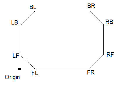
Adding an "r" makes CabMasterPro calculate the coordinate relative to the face origin. The origin of the face is the front left of the face, as it would be positioned if there were no chamfers. In a simple case of a rectangular face, this always makes the front left x and y coordinates zero. See Face Coordinates tutorial for more complicated situations.
You can do this with either style of formula. That is, you can write
Top_face.blxr (adding r at the end to make relative), or
Top_face.xr[1] (adding r before the brackets [ ] makes relative)
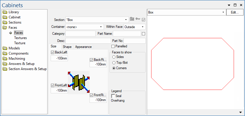
Here is a simple example with both styles of formulas. Load the drawing CornerChamfer-VertexPostionProperties.qid into CabMasterPro.
There is just one section called Box. It has a corner chamfer (an overhang of -100mm) set here:
Example .qid Faces page
In this screen grab, Machining view is selected in the preview pane, as it is more convenient when examining the machinestep polys discussed below.
Click to expand
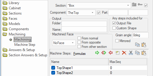
The section called Box has just one component called TheTop and that has two (2) machinesteps called TopShape1 and TopShape2 to illustrate these formulas, called TopShape1 and TopShape2…
Click to Expand
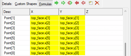
TopShape1 is a PolyLine with 8 vertices. Each vertex uses vertex name formulas .lbx .lby for Point[1] then .blx etc like this...
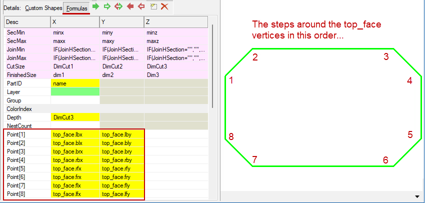
Machining > Machine Step: TopStep1 uses the face and vertex based system - Click to Expand
TopShape2 is the same PolyLine but instead each vertex uses vertex array formulas like ...
Machine Step: TopStep2 uses indexed naming system - Click to Expand
In both cases, the values are the same - this is just using two (2) ways of naming each vertex...
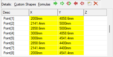
TopStep1 and TopStep2 have the same values
For example, the left end vertex on the back edge is called left back.
It can be referenced as top_face.lbx, top_face.lby
or equivalently top_face.x[1], top_face.y[1]
...which in both cases evaluates to the point 2000mm, 4858.6mm
The vertex at the other end of the little back left corner is called the back left, instead of the left back.
It can be referenced as top_face.blx, top_face.bly
or equivalently top_face.x[2], top_face.y[2]
...which in both cases evaluates to the point 2141.4mm, 5000mm
And so on around the 8 vertices in this example.
In the simple corner cabinet shown, we might be machining a shelf using the vertices ABCDEF. This is simple enough in this case but becomes much more difficult when the corner cabinet is angled and/or the corners themselves are chamfered. We can use relative coordinates to get coordinates of a selected vertex in coordinates relative to some other origin instead of world coordinates. When we used "r" in the previous paragraph, that origin is the origin of the current face. If we use "s" instead, then the origin chosen is the origin of the "other face".
Example : Simple Corner Cabinet
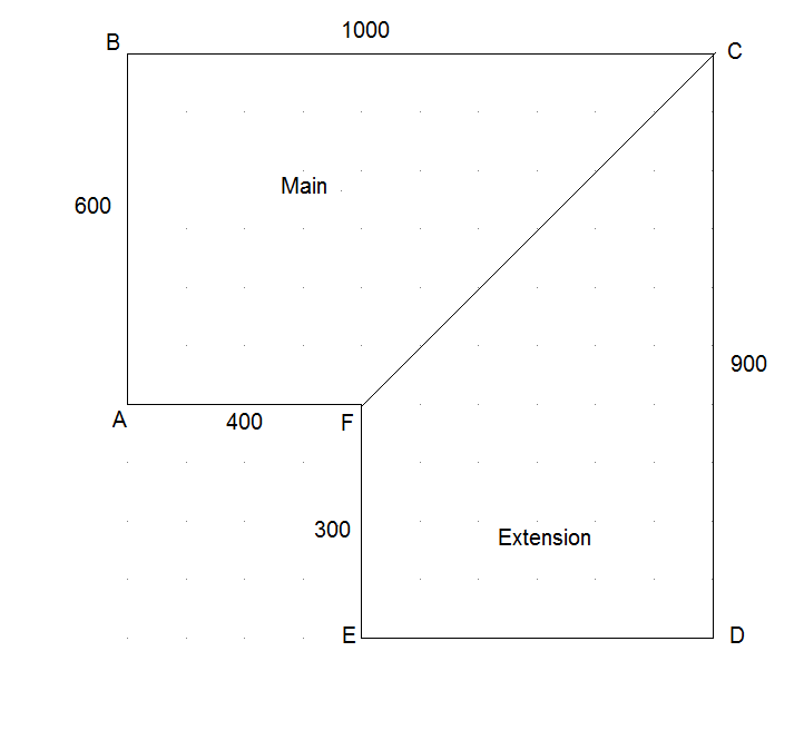
In the example shown, we will machine a cutout for the entire shelf in main part coordinates. To do this, we will need to get the vertices of the extension part relative to the origin of the main part.
We are able to use relative coordinates for A,B and C as follows:
Note that we can specify C and F using both systems. C is the back right of the main but is also the back left of the extension. Similarly, F is the front right of the main but is equally the front left of the extension.
Notice that for D, E and F, the vertex formulas use othersection.top_face to get to the vertices of the extension face. As a result we are in the context of the extension topface, so if we used .brxr (relative), it would evaluate in the coordinates of the extension top face. That would mean not only a different origin, but also the axes point in a different direction. The x-axis runs top to bottom for the extension face coordinates. When we specify .brxs instead of .brxr, the coordinate system used is changed to "other" and this actually brings things back to using the main top_face's coordinate system. That is how we get all coordinates calculated relative to the origin of the main top_face, which is what we want here.