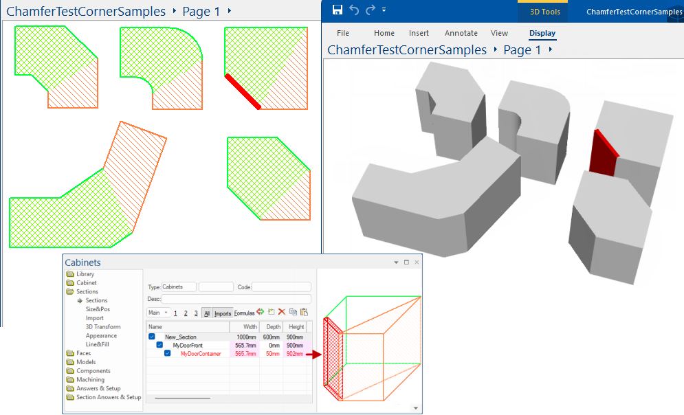

This tutorial describes the handling of diagonals in Corner Cabinets, in which the main section owns the diagonal, rather than the extension. This allows us to build some previously unsupported shapes.
v7.2.0.89 and earlier versions
In 7.2.0.89 and earlier versions, we could chamfer the back diagonal corner only, which divided up the diagonal like this, where we make the "main" and "extn" each take a share of the chamfer.
These shapes became whatever they needed to when we had a non-uniform (splay) chamfer at the corner, and the two sections mysteriously cooperated so the join ended up geometrically correct. These two parts are not only fairly useless for further section construction work, but things get even more complicated when we add a fillet curve to that back corner. Without further internal adjustment, it ended up as a pair of bumps instead of one rounded curved.
In version 7.2.0.90 and later, we decided a much better approach is to declare that the "main" should take ownership of the chamfered diagonal.
v7.2.0.90 and later
In version 7.2.0.90 and later, we declared that the "main" should take ownership of the chamfered diagonal, still getting its spec from the main and extn back corner chamfers, while the "extn" should relinquish ownership. So instead of the above showing sharing of the chamfered areas, it now looks like this....
Then everything becomes a lot easier: there is just one face at the back and we can easily make it a fillet rather than a chamfer if we want. Suddenly we also have a bunch of other new things we can now do that were never possible before:
The inner diagonal corner is easy to support (and is now supported for chamfers and fillets), and if you choose a chamfer that goes all the way to the far corner, you end up with the elusive 5-sided corner cabinet we have been wanting to properly support for a long time.
Here are some examples of what you can now do in 7.2.0.90 and later. The screenshots below will hopefully give you some new ideas and make it a whole lot easier to build some of these previously unsupported shapes.
Use the link here to download the sample drawing (.qid) that is screen grabbed below. Open with no library selected i.e. <none>.

In the above....

The only other thing we need to do is overhang the red door in height and width ever so slightly so that it appears in 3D properly instead of clashing.
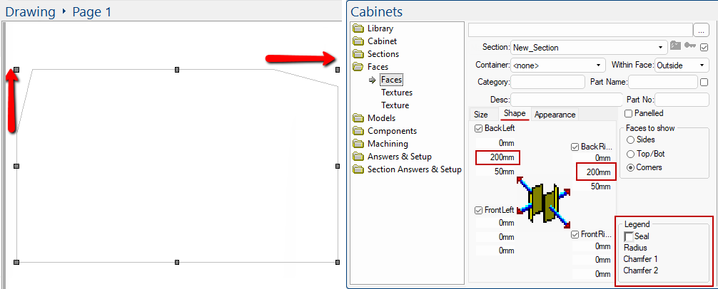
Note also, that when dealing with chamfers across the diagonal corner, you automatically get the ability to type in two different values...
In general, we traverse a section (main or extn) clockwise when defining chamfers, and chamfer1 is "into" the corner and chamfer2 is "out of" the corner.
For the diagonal "corners", that means chamfer2 for the main back right corner would be on the yellow diagonal:
In the above diagram, chamfer1 does come from the back right corner chamfer1 spec in the MAIN (heading into that back right corner).
But chamfer2 in fact comes from the chamfer2 spec for the back left corner for the EXTN (heading out of the corner and down that black back edge).
There is now a user interface to let you specify chamfer1 and chamfer2 separately. In the diagram below, the red arrows represent chamfer1 in both cases.
