CabMasterPro User Guide
 This document will outline the construction of corner cabinets, particularly focusing on the use of join methods. A join method has to do with the point where sections meet in a corner cabinet, and the way in which they interact at that point.
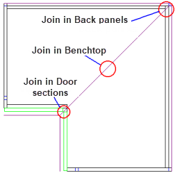
The diagram here shows joins between several sections of a typical corner cabinet. The major dividing line, which is between the Main and Extn (extension) parts of the cabinet, runs along the diagonal line from the inside corner to the outside corner. In a symmetrical cabinet like this one, every other join lies somewhere on this line.
To explain the types and uses of joins, we first need to understand how corner cabinets work.
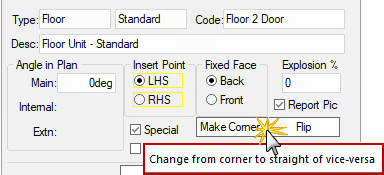
You can place a normal (straight) cabinet on your drawing, the Cabinet > Sizes page looks like the example. If you then press the "Make Corner" button, it warns you that this action is not reversible and then creates a corner cabinet.
Cabinet > Sizes page - Click to Expand
The Cabinet > Sizes page now allows the allows you to select which Cabinet Half you are working on, shown below. The two halves of a cabinet are "Main" and "Extn" and can almost be treated as separate cabinets. Each of these has independently named (but often the same/corresponding) HSections (horizontal sections, or just sections). In the middleware there is even the concept of othersection so if my section name is "shelf1" and you happen to be in "Main", then "othersection" refers to "Extn" "shelf1" which is useful for matching up machining etc.
Cabinet > Sizes page - Click to Expand
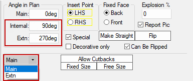
Corner cabinets are constructed in two distinct parts, known as Main and Extn (extension). They can be thought of almost as separate cabinets, which are merged together at an angle to form a corner cabinet. You can make a cabinet like this by clicking the "Make Corner" button, which is on the Sizes page of the Cabinet Property sheet. On most property pages is a short drop down list, from which you can select "Main" or "Extn" - this determines which half of the cabinet you are currently working on.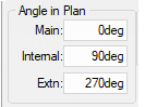 To set the angle between the halves of a corner cabinet, change to the Sizes page of the Cabinet Property sheet. Here you can set the Internal angle, which is the angle between the Main and Extension parts.
The two parts of a corner cabinet cannot just be stuck together - you need to define how each section in one half joins up with its partner in the other half. Two sections are determined to be a pair if they both have the same name. So if you want two back panels to match up properly, where one is in Main and one is in Extn, each panel needs to be called exactly the same thing. 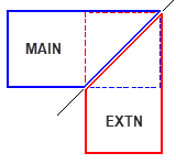 This is how CabMasterPro figures out that a join has to exist between these two corresponding sections.
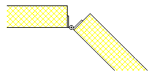
A trap that you should make sure you do not fall into is when you have one door on one half of a cabinet, and two doors on the other half. The natural impulse would be to call the single door just "door", and the pair of doors something like "door_left" and "door_right". This of course means that the two doors that are supposed to match up will not do so. Remember that they must have exactly the same name to form a join. In this case, you could make a single section called "door", which would be a container for the actual door sections "door_left" and "door_right".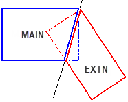 As mentioned above, the dividing line in a corner cabinet is where the Main and Extn parts connect. The depth of each part, and the angle they are joined at determines the position of this join. The line runs from the back corner to the inside front one, and defines the edge of the cabinet halves. All this means is that where the Main part joins to Extn is the right hand face of Main, and also the left hand face of Extn. Every section in the cabinet that uses the nominal dimensions as its container will take the shape of the cabinet half it is in. These diagrams show some examples of the dividing line, which is shown in a darker colour. You can see how the halves are "cut off" at this line - they become a trapezoid shape instead of the original rectangle.
 The join method of a section can be set by changing to the Sections Size and Pos page of the Cabinet Property sheet. Make sure you have selected the correct half that you wish to work on from the drop down list, either Main or Extn. Note that two corresponding sections (one from each half) can have different join methods. Examples of using two different join methods on corresponding sections can be found in the topic below titled Joint Types.
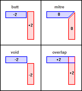
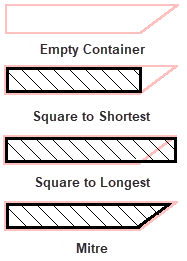
The mitre is the simplest and perhaps the most common join method. All it does is make the section take on the shape of its container along the dividing line of the cabinet. Since the dimensions of the container are going to be related to the nominal sizes of the cabinet half (and may be equal to the nominal sizes), this normally results in the end of the section being angled. If the corresponding section in the other half is also mitred, this will give a nice flush angled join (see Join Types below). On the illustration at the start of this chapter, the line marked "Join in benchtop" is an example of a mitre. The value of JoinMethod for mitre is zero.
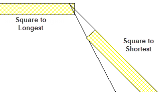
Two other join methods available are "Square to Longest" and "Square to Shortest". As the name implies, these will always give a square end to a section, the difference between the two is the position of the end.
Since the container of the section is going to have an angled side edge (where the two halves meet), the front and back face of the container are going to have different widths. All that Square to Longest / Shortest does is make the length of the section equal to the width of one of these two faces. For example, "Square to Shortest" finds the shorter of the two lengths, and makes the section that long. Its not as complicated as it sounds - see the diagram above (next to Join Methods).
The "Square to Shortest" method can be thought of as cutting off the angled end of the section just enough to make it square. "Square to Longest" is like adding on a small angled piece to also make it square, and the same total width as its container. The JoinMethod variable has a value of -2 (minus two) for "Square to Shortest", and +2 for "Square to Longest".
"Square to Back" and "Square to Front" are very similar to "Square to Longest / Shortest" except that the length of the section is determined by either the front or back face of the container, not the shortest or longest of the two. This is because in a "normal" cabinet (e.g. one at 90°), the back face is longer than the front face. So "Square to Shortest" was usually used instead of "Square to Front", and "Square to Longest" was used instead of "Square to Back".
As you can see from the picture above, this is not always the case - the Main part has a back face which is shorter than the front. So by using these two join methods, you can specify exactly what you mean, and it will work regardless of the angle the cabinet halves meet at. "Square to Front" results in a value of -1 (minus one) for the JoinMethod variable, and "Square to Back" gives +1.Examples : Butt, Mitre, Void and Overlap
To get the expected result every time when dealing with joints between panel sections (such as doors and backs), the cabinets need to be constructed in the correct way. This is especially true for corner cabinets that have an internal angle other than 90 degrees. Most construction methods will appear to work OK with a right angle corner cabinet, but will break when the angle is changed. Even if you are going to fix the internal angle at 90°, it is still beneficial to make sure you construct your corner cabinets in the correct way every time.
One common construction method (using back panels as an example) is to create a section inside a container such as the carcass, and set it to have a "Fixed Depth", measured "Forward from Back". This would work fine in most cases for a normal (non-corner) cabinet, and also in a right angle cabinet. However, in an angled cabinet, using this method can have disastrous results, as shown below.
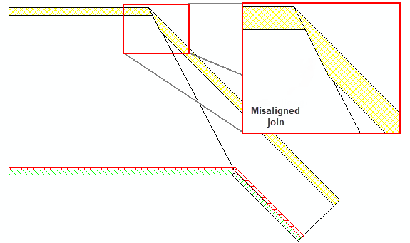
Both of the back panels in the picture are constructed as described above, and use the mitre join method. Because mitre makes them take the shape of their container, the edges follow the major dividing line between the two halves. Even though it doesn't look it, the panels actually are the same thickness, but because of the angle the joint is not properly formed.
Example : Misaligned join
The outcome is even worse when we use a different joint type, such as a butt joint. This is illustrated in the diagram below, which shows the same zoomed in section, except using Square to Longest on one panel and Square to Shortest on the other. This arrangement would work correctly only if the internal angle of the cabinet was a right angle (90°). It is also easier to see here that the panels really are the same thickness.
Example : Issue with using a different joint type
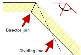
The only real good solution for a problem like this is to have a mitre joint that ignores the angle of the main dividing line. It needs to cut across both back panels at the same angle so that the cut faces are the same size and match up exactly. The angle that we want is the bisector of the back faces, where bisect means to cut the angle into two equal parts. A diagram of the bisector join is shown here:
Example : Solution to issue
This technique could be also used for the containers of sections. If the sections themselves were then set to be "Square to Shortest", you would get a result like the one shown here, which would be especially useful for joins between doors.
Example : Corner Piano Hinge
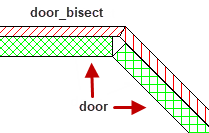
To make a bisector joint like these, we can put another section "in between" the door or panel section and its container. By in between, we mean that the intermediate section goes inside the carcass, and then the door goes inside that section. This section therefore becomes a container of the door. We will call this intermediate section "door_bisect", and it will only be used for determining the bisector angle so will not appear in drawings.
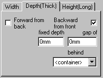 To start off, create a new section called "door_bisect", which will have a container of "carcass" (or whatever the container of the door section was). On the Section > Size & Pos page of the door_bisect section, change to the Depth sub-tab and uncheck the "Forward from Back" box. It should end up looking like the one shown here. What this results in is a section of zero thickness on the front face of your carcass section. Make sure that the join method of this section is set to "Mitre".
Now change to the Faces page of door_bisect, and overhang its back face by 10mm. This is an arbitrary distance, and is only to give the section some thickness and to make it visible on the cabinet during construction. Back on the Section > Size & Pos page, select the door section and set its container to door_bisect. Check the "Forward from Back" box, and clear "Backward from Front". You should now be able to enter the thickness of the door in the "Fixed Depth" box, typically by formula control.
The next step is to go back and repeat all this by creating a corresponding door_bisect section in the Extn half of the cabinet. When you are done, the join method of both door sections can be set as desired - in the diagram here they are set as "Square to Shortest".
Example : Square to Shortest
This is only a simple example, for real doors you would have offsets from the front of the carcass, and hinge recesses on the sides of the door, etc. The point of the exercise is to get two sections along a face to mitre at the bisector angle. Once you have these, sections inside them can be built in any way you wish.
The final step is to hide both door_bisect sections, so they do not show up in drawings. You can do this by changing to the Sections > Appearance page and unchecking "Show Section". Make sure "Show Content" remains checked, otherwise the doors will be hidden.
On the Section Size & Pos page is a checkbox marked "Flush Corner", which is used when joining sections in corner cabinets. All it does is ignore any recesses or overhangs on the face that lies along the dividing line.
For example, if the face at the join was recessed for a door gap, checking the "Flush Corner" checkbox on this section would ignore the gap and make it the same width as its container. If the corresponding section in the other half also had "Flush Corner" checked, both sections would be touching each other because neither side would be recessed. On the Faces page, the section's join face of would be hidden to indicate that it cannot have an overhang while "Flush Corner" is set.