CabMasterPro User Guide
In version 8.1, flaps in remote components were implemented via the donor/acceptor logic. For introduction to donor/acceptors see Donor Machine Steps tutorial.
In version 9, flaps no longer use donor/acceptor steps. Instead, the section structure is used to determine how components get combined.
Consider the example where you have a panel A and a flap B. In version 9, sections A and B need to be placed in a third container section which indicates to the program that A and B are meant to be combined. Sections A and B are specified in terms of custom shapes.
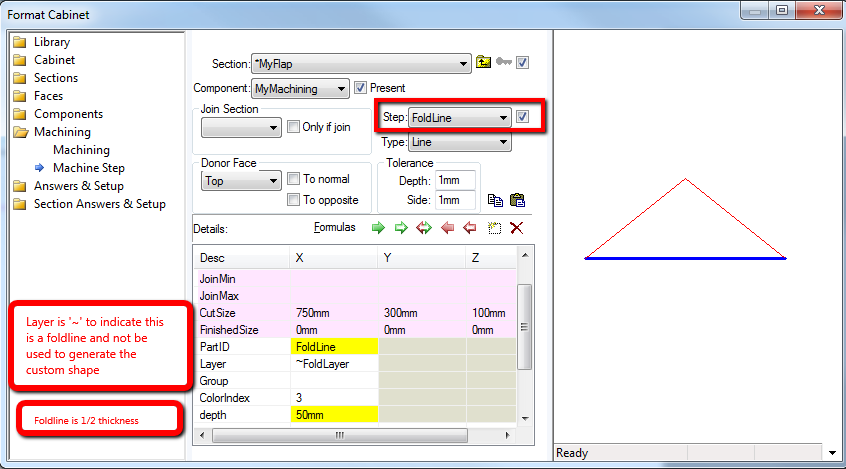
When the layer value is prefixed with '~' it indicates that this step is not to be included in the custom shape. It will not try to "notch" or combine with the "acceptor".
Note that the support for remote components means the notching or flap machine step can be defined and come from another section, which could even be imported. For example you could have a collection of flap shapes in a sub library.
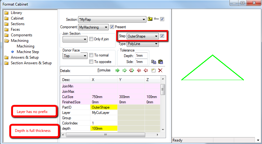
The following example indicates the new use of the layers and step settings:
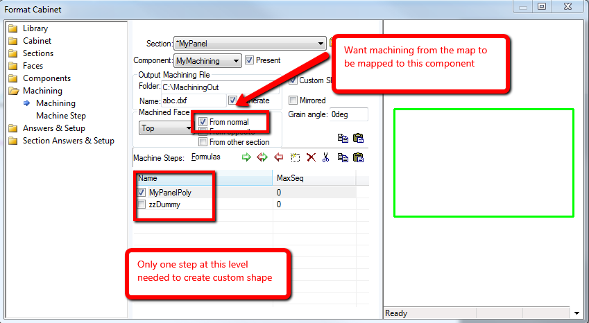
In this example, we have three sections: Container, MyFlap and MyPanel. The MyFlap and MyPanel sections each have a component, with the machining set up in the following way:The Output Machining File is specified the same for both components (In this case it is "C:\MachiningOut\abc.dxf"). The Custom Shape check box is ticked for both components. Importantly, the "From Normal" for MyPanel is checked which indicates that we want to map any combined machining from other components to its coordinate system, rather than vice versa. The Generate flag needs to be set or a warning message will be issued indicating that machining may give unexpected results.
Looking at the actual machining, we have just three machine steps...
FoldLine is for the half depth V cut, in this example, which defines the tool and depth of this fold.
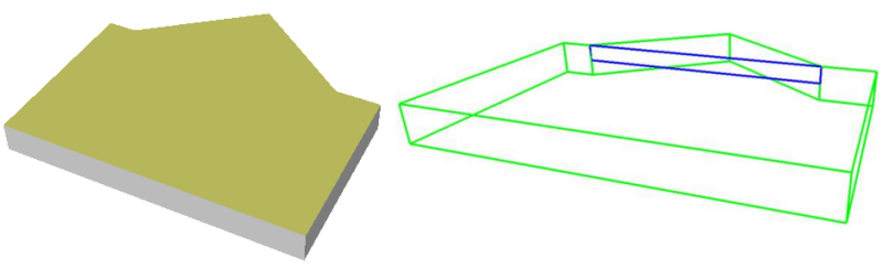
When we go into 3D, we can see the generated custom shape (below left) and in wireframe machining view, we can see the fold line (note that it is half the thickness).