Creating and Editing Capping Profiles : Developer
In This Topic
Capping profiles are stored in QPF files. These are simple text files with each line containing an x,y coordinate for a point. The x and y values are tab separated. The sequence of lines traces around a shape which is nominally in a square from (0,0) to (1,1). Always trace around the shape counter clockwise, or the 3D will be "inside out".
The actual sequence can go outside this square or wherever it likes. But the unit square is the reference area that is stretched or moved to where it is being applied to generate the actual capping shape in .
The easiest way to edit capping profiles (QPF files) is to export to an HPanel, edit the HPanel, then import back into a QPF. This lets you use all the HPanel drawing tools - snapping, exact measurement, dragging points around to change a profile, adding or deleting points, filleting corners and so on.
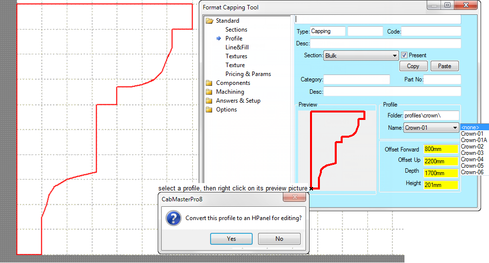
To go from a QPF to an HPanel, you right click on the Preview button in the capping tool and it prompts you, asking if you want to convert it to an HPanel. This creates an HPanel at 0,0 in the current drawing. Note that the unit square from (0,0) to (1,1) is scaled to an HPanel of size 1000mm x 1000mm for ease of working.
Start with an empty drawing, double click on the capping tool, select a profile, then right click on its preview picture. This prompts you to confirm that you want it converted to a HPanel for editing, select yes and proceed to edit:
To go the other way, from an HPanel to a QPF, you right click on the HPanel and select "Export to Profile QPF...". Then enter the filename.
Note that the export QPF function automatically scales the HPanel by dividing by 1000mm. It also ensures it is traversed in counterclockwise order. That is, if you draw it in clockwise order, it is automatically reversed so the QPF file is always counterclockwise as required.
Hints for creating QPF's
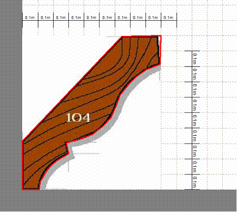
- Sometimes the profile you want to draw comes from a photo or brochure. If you scan the profile in to a program like PaintShop Pro, you can clip to the shape of interest, then load it into as a bitmap. Then you can scale to occupy a 1000 x 1000 square and click on a sequence of points to make an HPanel of this shape. This is often the easiest way to create the desired shapes. Here's an example, where we also included a scale on the bitmap:
- Use the status line in to observe the coordinates if necessary when working with the HPanel. It is easiest to set units to mm - remember the unit square is scaled to a 1000mm x 1000mm HPanel.
- HPanels can also be exported to DXF and viewed in AutoCad or Voloview.
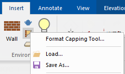
- Capping Tool setups can be quite complex, so be sure to use the Load and Save right click options on the tool itself, to save your setups in QTD files. This will use the subfolder ToolData\Capping by default. (Each tool saves QTDs to its own ToolData subfolder).
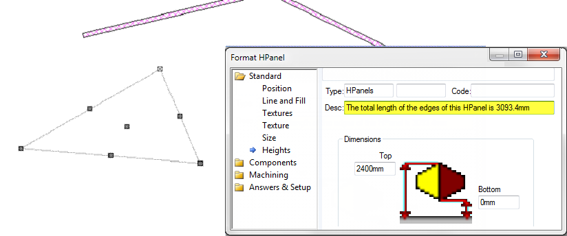
- There is a middleware built-in variable called TotalLength which calculates the length of the capping sequence. See Built In Variables
This can be used to calculate costs. It only refers to the baseline sequence, so you may need to apply a small markup to correct for mitres and the effect of overhangs.
Note that TotalLength also works for Walls and HPanels. For HPanels it corrects as necessary for any closing line. Here's an example:
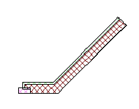
- Sometimes you can get strange 3D effects when you accidentally click an extra time while creating capping. If you look carefully at the 2D view, you will usually be able to see this as a strange effect there too. You can confirm the doubling up by an ascii export. Visually the effect will look like:
- Textures map across the whole piece of capping, as you would expect. Here's an example, showing a texture with writing applied:

See Also


