CabMasterPro User Guide
This document will explain custom shape and machine editing support for edge profiling.
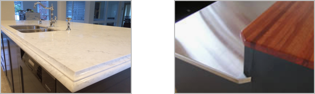
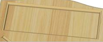
Using custom shapes we can set up an edge profile for both outer edges of a benchtop and holes (e.g. for sinks). Some edges, for example, will be square cut as pieces of benchtop need to join together or hit a wall. In practice there can be a mixture of profiles on one piece of benchtop.
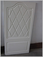
Here are some examples:
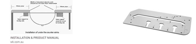
Holes may also be profiled e.g. with pencil rounded edges for sinks and sometimes more complex.
All of these shapes can be implemented using custom shapes, by having a stack of contours with varying offsets in the xy-plane.
The custom shape machine step defines the control shape which has a depth in the z-direction.
The profile can be defined by an XML file which is based on the QPF format already supported for capping. The XML gives a sequence of offsets at different z-heights.
These offsets are then applied to the control shape to give the 3D custom shape for viewing.
For freeform machining using the CabMaster Machining Editor, we can arbitrarily alter the control shape, applying fillets, chamfers, notches, arcing edges, dragging corners to new locations and so on. If the machining editor alters the number of points in the polyarc, it has to also adjust the "edge spec" array.
There are three new MachineStepEntry (MSE) rows in the machine step grid for polyarc shapes.
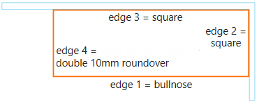
We could specify this as:
ProfileFolder "MyProfiles" ProfileName ["Bullnose","Roundover"] ProfileEdges [1,0,0,2] This would look for the profile files "Bullnose.xml" and "Roundover.xml" in the "MyProfiles" subfolder of the current BitmapFolder.
It would keep edges 2 and 3 square (no profiling) but would apply offsets to edge 1 ("Bullnose" profile) and edge 4 (double "Roundover" profile).
If we drag a corner of this rectangle to make a different shape, no changes are needed to the above spec, it will just work, profiling by applying offsets to the new control shape.
If we use the freeform Machining Editor and chamfer the front left corner, then the editor will update the ProfileEdges array to [1,0,0,2,2] adding a 5th edge spec, by default same as the 4th.
The same spec and interface applies to holes, such as sink cutouts and also limited depth edge profiling will be supported as well.
DXFs created will export the polyarc control shape that the user ends up creating...
For example, the above shape will be exported as edge 1 in layer "Border_Bullnose", edge 2,3 as a poly in layer "Border" and edge 4 in layer "Border_Roundover".
By selecting appropriate layer/strategy mappings in EzyNest, the shape will then be correctly machined with required profiles per edge.
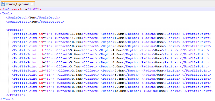
The XML file has a section which defines the shape of the edge profile in the vertical plane. The sample provided is for a Roman Ogee shape.
The XML file has a sequence of offsets at each depth, like this...
The XML profile file also carries the scaling rules:
ScaleDepth YesNo (no=use raw values) ScaleOffset YesNo (no=use raw values)
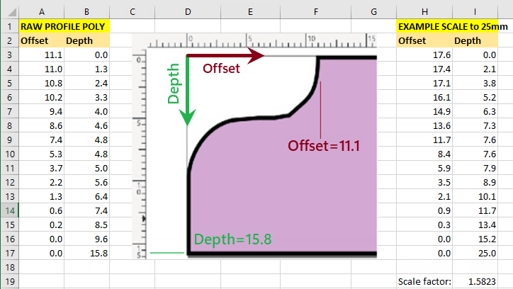
If ScaleDepth is Yes, we take the shape and stretch to cover the part depth (say 25mm). This is done by multiplying the raw profile poly depths by 25/15.8 (since 15.8 is the maximum depth in the profile poly as defined). Depending on how the ScaleOffset flag is set (yes or no), the offsets will be left as they were or scaled by the same factor.
The calculations are shown in the spreadsheet:
The sample XML file has id="1" etc attributes for the nodes, but these do not have to be present and are ignored. There is also a radius. This allows you to specify the shape more accurately and with less points, as a polyarc. In this example the radiuses are all 0mm, so this is just a polyline shape. These radius values are the radius of curvature to the next point.
In practice, the part depth is specified in a MachineStep as CutSize.Z. This strictly is just the component depth but typically comes from the section depth via formula control, so this is the overall depth of a part (panel, shelf etc) as it appears in 3D. An edge profiling machinestep has a tool penetration specified separately as the machinestep Depth.
These are not necessarily the same, and there are lots of different situations. For example, with the depth of cut less than the part depth, we are just using the tip section of a tool that is longer than the depth of the part, like this:
If we are profiling the edge of a door, (held up on supports, say), then the tip of the tool can go to a depth beyond the part depth. Here's the same tool as above, now cutting to a depth beyond the part depth:
In these two examples, the xml tool shape is taken literally (ie no scaling), but for artistic effects, we can use the values in the xml file with scaling. They can be stretched (or shrunk) across full depth of a part. If the xml ScaleDepth attribute is set to Yes, then the shape of the tool is stretched or shrunk to the part depth, like this:
Here the offsets remain as their unscaled (raw) values, but if the xml ScaleOffset is also set to Yes then the scale factor required to make the tool depth fit to the part depth is calculated and also applied to the offsets, like this...
These examples show the tool profiling the edge of a part, but an xml tool file can also be used on open contours in the middle of a part. For example we can use a V-cutter tool to cut veins, or decorative grooves, in a desired pattern on the face of a part such as a door. In this case, setting the depth to different values will cut veins at different actual depths.
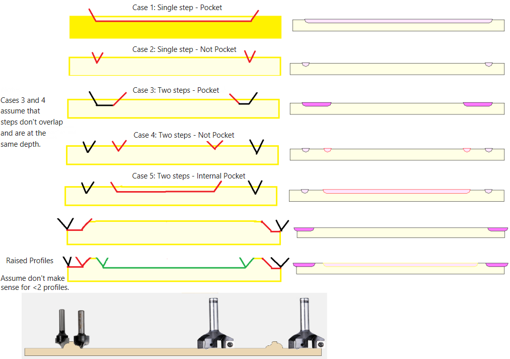
The Pocket machinestep entry is a yes/no determining whether the area inside the machinestep is to be removed. Applies to contours (closed polylines only).
A profile is defined via the ProfileEdging specification. It determines the shape of the actual cut at the sides of the polyline. Often these cuts are done using a shaped tool such as an Ogee cutter, rather than a simple V-cutter tool. But the cutting can either be a cut along a closed polyline shape, with material left inside like this…
Or it may be that the inside area needs to be entirely cut out like this…
When the internal area is cut out, this is referred to as a Pocket.
The two cases are set up with exactly the same Profile details, but in the case of the Pocket, we just set the Pocket entry (X value) to Yes instead of blank or No.
The situation gets more complicated when there are multiple profiles specified, for example two concentric closed polylines. The most commonly used options are summarised in the diagram below, where the simple case of just one profile with Pocket set to Yes is case 1 and Pocket set to No is case 2.
The diagrams show the elevation or edge view of the cuts, as though you have sawn across the middle of the above images and you are looking at it edge on, giving a cut on the left and a cut on the right: