
Profiling machinesteps use XML for the profile definition. If profile machine steps are used, a Profile tab will be provided so that you can switch between Plan View and Profile View.
Download the ZIP DoorProfilingSample.qid and the two XML files (OgeeP1.xml and V45.xml) used for this discussion and extract files.
These files all need to be in the same folder (not necessarily the data folder).
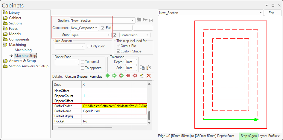
Machine Step : Ogee
This Machine Step uses the provided OgeeP1.xml file.

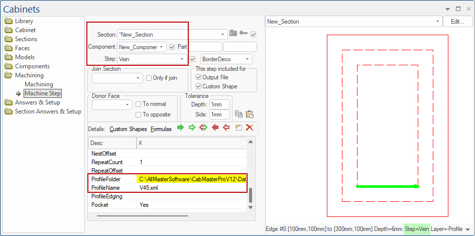
Machine Step : Vein
This Machine Step uses the provided V45.xml file.

On opening the provided qid file, you will see the following door...
Use the Breadcrumbs Bar to locate the part New_Section, as shown, then...
This allows you to use the tabs to switch back and forth between Plan View and Profile View.
A Grid can also be enabled by ticking the checkbox on the View command ribbon (as shown above). It is available in every view and is quite useful in particular in Profile View.
As you zoom in, the grid redraws to provide an appropriate resolution for current scale. For convenience, the “Model” XY coordinates on the status line can be used to examine the profile XML.
In the following example, the Model coordinates of the top left red point of the V cutter shown below is X: 87mm and Y: 5mm.
If you click on it, then move the mouse to the next point just below and to the right, you can see both the Model coordinates and the Delta offset from the clicked-on point.