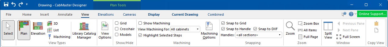
In This Topic
To locate information about any commands or tabs,  click on the area of interest on ribbon image above.
It allows you to select one (for editing) or multiple cabinets/items at the same time which allows you to copy/paste for faster reproduction of previously drawn cabinets/items.
Context tabs are dependent on the View Type selected and are shown only when needed to reduce clutter.

For example Plan Tools, Elevations and Cameras tabs, are made available only when the View Type is Plan.
The View > Plan command button changes the display mode of the active pane to a top-down plan view of the drawing.
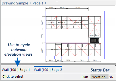
All views can also be accessed from the Status Bar, including Plan - 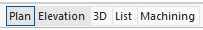
Refer to Split for details on how to display more than one view at the same time.
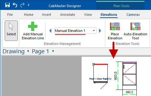
The View > Elevations command only works if there is an elevation on the Plan. It changes the display mode of the active pane to a side-on elevation view of the drawing.
Elevation views are automatically created along each wall
You can also use the view tabs to cycle between Elevation Views.
Elevation views are automatically created along each wall in a drawing but you can also create manual elevations of selected cabinets etc.
If there is no wall then a message 'No elevations to display...' is presented. You can, however, create a Manual Elevation Line in Plan View.

Manual Elevation
The View > Elevations command only works if there is an elevation on the Plan.
This is the same cabinet displayed in Elevation Mode.
Labels and any number of text boxes, pictures and extra dimensions can be added - see Tutorials on Elevations.
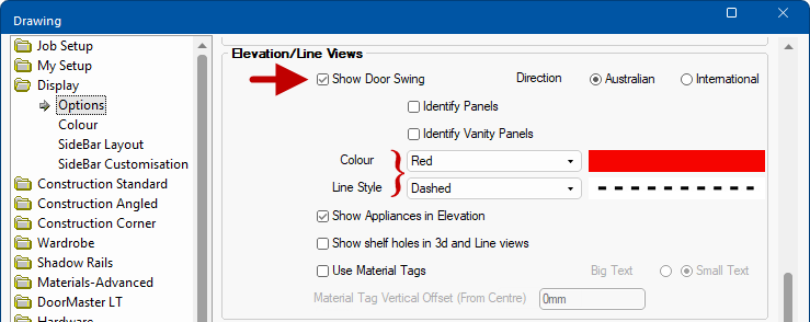
Elevations can be further enhanced by turning on/off the Show Door Swing option on the Display > Options page  of the / Properties [F4]. The colour and line style, and more, can also be changed here.
Display Options for Door Swing
Changes the display mode of the active pane to a three-dimensional rendered view of the drawing and the Display tab becomes available. See the tutorial on Generating A 3D Image.
Changes the display mode of the active pane to List View i.e. a listing of all the items currently on the drawing.
In this view, this includes library items which have no visual representation in the plan can be added. Items which do not represent any physical items such as freight etc can also be added, allowing pricing information to be added independent of any specific cabinet. All items added here will be included in reports and other exported information about the drawing, even if they are not visible in the plan view.
Changes the display mode of the active pane to allow selection of Machining options, integrating directly into .
The Library Catalog Manager allows the end user to create their own libraries (.qim) using the 'BasedOn' library (.qil) supplied.
Only available with .
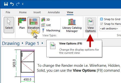
Keyboard Shortcut: F9
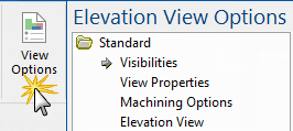
The View Options [F9] available are dependent on the View Type, as shown, and allows for customisation of display options for the current view.
As well as the command buttons on the View and Display tabs (click on image), you can use the keyboard shortcut F9 which works in all views or, if in Plan or Elevation View, simply double click on a blank area of the drawing page.
Click to view an example and more on the various ways to access View Options
For a detailed discussion, see the topic on the View Options [F9]
Machining Options* are only made available if the Show Machining option is enabled in 3D Display with Wireframe.
Toggles the display of the grid, which is drawn as a set of dashed lines on the page. This grid is only used as a visual aid when drawing, and does not appear on the printed page. The spacing between grid lines can be changed - See Grids and Snap tutorial.
Toggles the display of a large crosshair which extends all the way across the drawing page. The crosshair is useful for aligning objects over the width of the page and is also used to Split Windows. It will Snap To Grid or Snap To Handle, if those options are enabled.
Checkbox to enable or disable 3D Models. Disabling improves rendering performance.
See Copy To File and 3D Photoview Companion Models tutorial.
These options are only available with .
The Show Machining checkbox, if enabled/ticked, will display machining in 3D Wireframe.
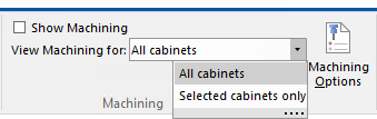
Show Machining also determines if the Machining Options page (click on image) of the View Options [F9] feature is made available, which allows you to use filters to restrict viewing to just the machining of interest (e.g. hinges or runners only) - see Machining Options discussed below.

Click to Expand and to view 3D View Options > Machining Options
View machining for selected areas from . The default is All cabinets but you can change to Selected cabinets only, so that machining will only be displayed for the currently selected cabinet.
Note that the Show Machining checkbox is turned off and the Machining Options is made unavailable (greyed out).
As stated above, machining can only be displayed when in 3D Wireframe mode.
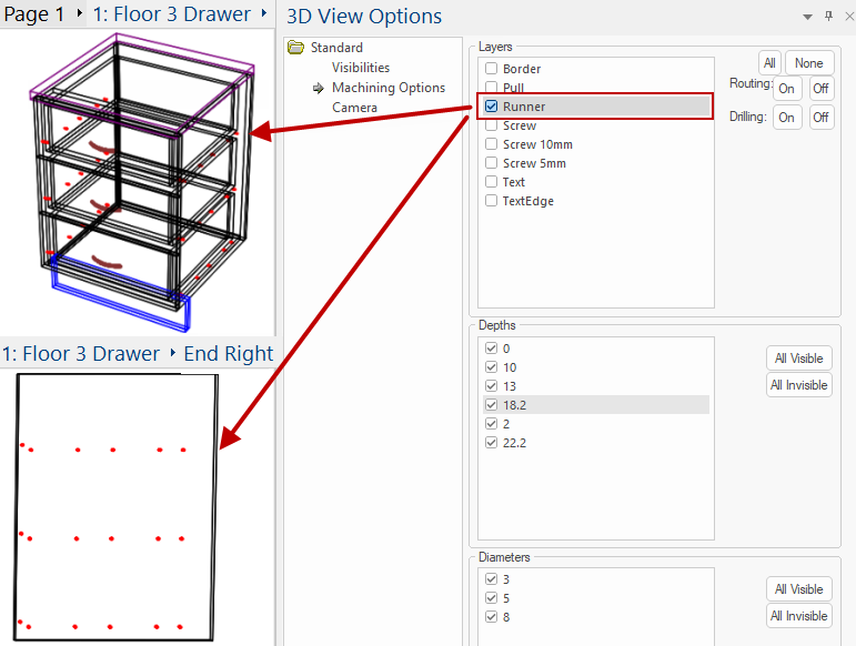
The opens a Machining Options Page which allows you to use filters and restrict viewing to just machining of interest (a layer, a depth range, routing or holes only, etc).
Example of restricted view
In this example, we only want to view the machining for Runners, shown in 3D for the cabinet and the individual part.
Enable Show Machining and use the checkboxes, shown below, to filter as required.
Snapping allows you to place objects flush up against other objects, perfectly aligned.
See the following for detailed discussions on...
Toggles the use of grid snapping, which means that any object placed on the drawing page will automatically be moved to the nearest grid point for accurate alignment.
You can have the snap grid hidden, yet still have objects snap to grid points. See topics
View Options [F9] and
Grids and Snap tutorial.
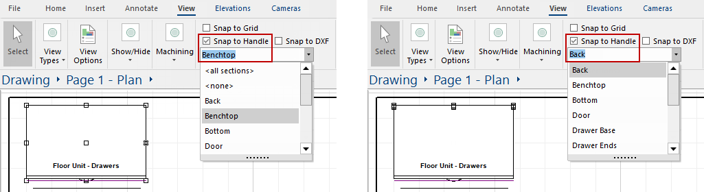
Snap to Handle & Handles
Snap to Handle provides the ability to toggle the use of handle snapping, which is not related to either of the grids.
Handles are the small squares on the corners and mid-points of objects, which you can drag to resize the object. Enabling handle snapping means that when you place an object near another one, the handles on its corners will try and align themselves with the handles on the other object. The object will jump next to the other one as its handles overlap, meaning that aligns itself exactly. See Selecting and Editing Objects Tutorial.
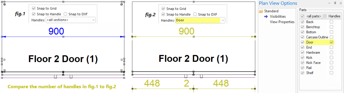
The Handles allows you to select the specific type of item you want to be able to snap to, from a list of sections in the current drawing. By selecting one, you will allow to snap to that section as well as the nominal cabinet handles. The allows you to select the specific type of item you want to be able to snap too, such as Door. Then only door items will have snaps available, making placing Dimensions much simpler. To resize an entire cabinet by dragging its handles, make sure the Handles selection is set back to <none> - see tip below.
As shown in the following example, in fig.1 <all sections> is selected and when you hover the mouse over the cabinet, all the handles are displayed. When you compare this with fig.2 where only <Door> is selected, the number of handles is limited to the doors and the nominal cabinet handles.
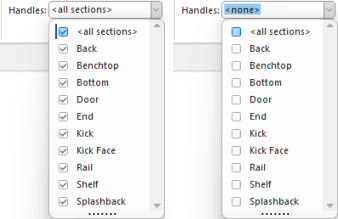
Be sure to set it back to <none> when finished by unticking the <all sections> option, shown right.
It is recommended that Snap to Handle be left turned on, because it makes accurately placing cabinets very easy. In some rare cases when placing odd-shaped cabinets, Snap to Handle may need to be temporarily disabled.
When selecting handles, you may find it easier to use the
View Options [F9] feature where
Handles can be turned on/off using the
Visibilities docked and readily available (
compare above Plan View Options), rather than swapping to the
View tab to use the
Snapping group of commands
.
The View Properties page also has a Handles selection drop check list for 2D/Plan views
This compares the options of the View command ribbon to the corresponding options available on the View Properties page.
This allows you to import a dxf, for example a house drawing, and zoom and pan to the kitchen area and use it as snap points to quickly draw the same walls, if the house drawing already provided an accurate layout. See DXF Snapping Tutorial which discusses how to import a DXF, scale and position it and use it as a snap target.
Changes the magnification of a view. Refer to Zoom for full discussion.
Window
In Split Screen mode, one View can be in 2D and the other in 3D. You can then click on the title bar of a View to make it active, e.g. for 3D Navigation.
Refer to the section on Panes tutorial for full details on how you can use the Split command to display more than one view at the same time.
Hides the taskbar, Titlebar and ribbon to give a larger drawing area. This is useful for working with 3D images or on small monitors. To return to the normal viewing mode use F11 or Close Full Screen button.
This will allow you to copy the current view to the clipboard as a bitmap. It can then be pasted into most image programs and saved or edited.
Saves the current to a bitmap file or a 3D format, if in 3D view, using Open and Save dialog. It will be exported from the current view position and angle, so the resulting image will look exactly as it does on the screen. Bitmap files can be opened in virtually all image viewing or editing programs. The 3D model will be exported in the 3DS file format, which can then be used to create photo-realistic renders.