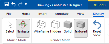
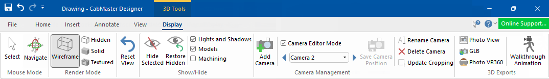
Display 3D Tools ribbon commands
In This Topic
To locate information about any commands or tabs,  click on the area of interest on ribbon image above.
This command ribbon is only made available when in View | 3D mode.
Mouse Mode
Select
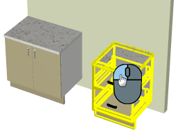
When Select mouse mode is enabled, the current selection/s are made visible by drawing an outline in wireframe on top in yellow.
Holding down the Ctrl key while in Navigate mode will automatically change the mode to 'Select' - see Mouse Shortcuts.
Deselect single items (i.e. one by one) by holding down Ctrl while using the left mouse button.
Deselect all items in one go, simply click on a blank area of the 3D page.
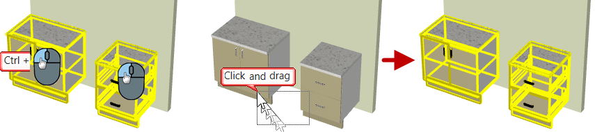
When Select is enabled, it changes to the Select tool, which allows you to highlight objects by...
- select one cabinet/item by left clicking on them individually;
- select multiple items by holding down the Ctrl key while left clicking individual items;
- or by clicking on a blank area of the drawing near items for selection and dragging the mouse to form a box.
- any objects inside or touching the box will become selected.
Navigate
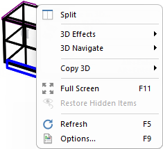
Clicking on Navigate button turns off the 'Select mode' and allows you to use your mouse to navigate or the right click 3D Menu, as shown below.
When in 3D Navigate mode holding Ctrl key, after selecting an item, next click should add another item to form a multiselection.
Click to Expand
Displays the current 3D image in Wireframe mode. It only displays the edges of each section and does not draw any flat faces. Wireframe mode is the fastest to draw because it is only a line drawing. It also allows you to Show Machining.
Displays the current 3D image in Hidden mode. Similar to wireframe, except that all edges that would not normally be seen have been erased. This makes the image easier to visualise, but takes longer to draw.
Displays the current 3D image in
Solid mode. Draws panels as single-colour surfaces, and takes slightly longer to generate than wireframe mode.
Displays the current 3D image in Textured mode, i.e. "Paints" photo-realistic textures onto each surface in the drawing.
CabMaster uses a default set of materials that can be customised to the user’s preference.
Moves the camera position in 3D mode back to its original position and angle. This is useful if you lose the image by accidentally moving it out of the view window.
Hide Selected/Restore Hidden 
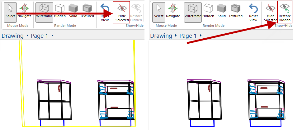
Selected cabinets/items can be hidden from view by using the Hide Selected ribbon command button or the right click menu (see example below). When items are hidden, a red tag with the number of items made invisible is provided and all allows hidden items to be made visible.
Make hidden items visible by clicking on the Restore Hidden command button (which is no longer greyed out) or the right click 3D menu.
Example
In this example on the left, the wall has been 'selected' and displays in yellow wireframe. Then the Hide Selected button was pressed.
The result is shown on the right, where the wall is hidden in 3D View. The Restore Hidden button is no longer greyed out and can be used to restore visibility.
Corresponding options are also available from the applicable right click menu.
The Restore Hidden button will restore all hidden items. To unhide selected/individual items, then use the Visibilities view filter discussed next.
See the tutorial on 3D View Filters : Hide/Restore, for more on Hide/Restore and Visibilities.
Visibilities [F9]
The Visibilities command button works the same as the keyboard shortcut [F9] when in 3D Display.
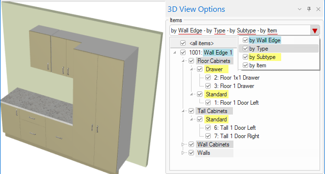
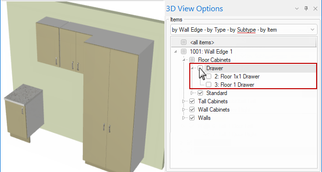
3D View Options has filtering hierarchical tree control to turn visibility on/off using the applicable drop menu list checkboxes at the top i.e. by Wall/Type/SubType/Item, as shown.
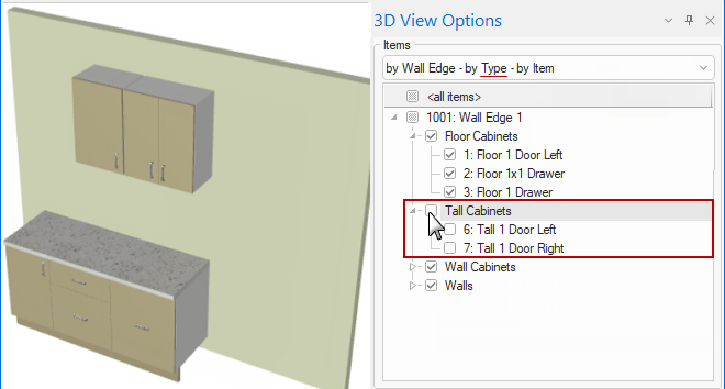
Example of cabinets turned on/off in 3D View
The following shows that the visibility of the Tall cabinets have been turned off (compare to image above).
This example shows that the visibility of the Tall cabinets have been turned back on but the Floor drawer has been turned off (compare to image above).
View filters can also be set up for any camera view (discussed below) and therefore for 3D Callouts in plan view.
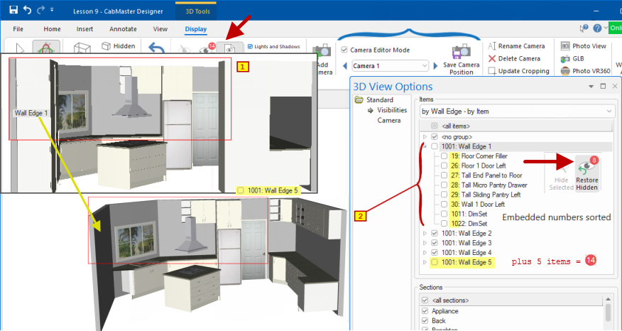
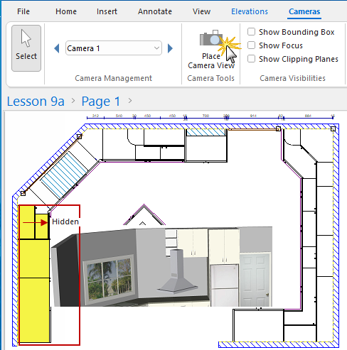
Example of Camera Editor Mode and Visibilities
In the following example, "Camera Editor Mode" is turned on and (1) Camera 1 selected and then (2) Wall 1 cabinets (8 items) unchecked/hidden.
When you have one or more Light items in a drawing, each light also casts shadows by default. Since this can greatly increase the time it takes to render a 3D image, this option allows you to temporarily disable the drawing of shadows. Once you have positioned the viewpoint correctly, turn this off to render shadows. It has a similar effect to unticking the
Casts Shadow checkbox on each
Light in the drawing.
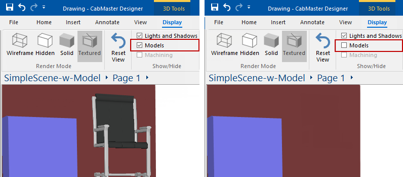
Since some 3D Models can contain more detail than an entire drawing, they can significantly slow down movement in a 3D view if many are used. To help increase the speed in 3D, unticking this checkbox will temporarily hide all models in the drawing. When the viewpoint is in the desired position, enable/tick this option to make all the models re-appear.
Example
The image shows a 'Model' of a chair displayed when the checkbox is ticked.
Each appliance cabinet also has the option to display as a 'Picture' or a 'Model'. If an appliance uses a 'Picture', it will not be affected and will remain displayed.
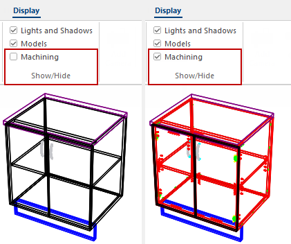
Machining checkbox can be enabled/ticked to displayed machining in 3D but only if Wireframe View is selected.
Example of Show Machining options and result in 3D, using commands on the Display and View tabs.
The Show Machining checkbox is also available on the View tab and, if enabled/ticked, will display machining in 3D Wireframe.
Show Machining also determines if the Machining Options page (click on image) of the View Options [F9] feature is made available, which allows you to use filters to restrict viewing to just the machining of interest (e.g. hinges or runners only)
Allows you to create multiple 3D views (i.e. Textured or Wireframe) defined as required i.e. you can zoom and/or crop portion of a view
These layout views can then be...
- added onto your Plan View to show additional details.
- It is like adding an image/Callout except that these camera views will update LIVE when you make modifications to your drawing.
- used to create a Walkthrough Animation.
See the Camera View Tutorial (which includes a video  ) for a detailed discussion on how to define specific areas and place on your Plan.
View filters can also be set up for any camera view and 3D Callouts in plan view.
This shows the camera view has used filters to hide the cabinets on Wall 1 (
click on image).
Click to view Camera added in 3D Display with added filters.
See the tutorial on 3D View Filters : Hide/Restore.
Camera Editor Mode
The checkbox turns on/off the editor mode for the camera.
You can create as many camera positions as you want by using the Add Camera command icon. These will automatically be added to the list of views.
If you make adjustments to a selected camera view, the Save Camera command will be made available (see Camera View Tutorial for more details).
You can also select camera views from the list and:-
- Rename
- Delete
- Update Cropping i.e. reselect and change the selected portion of the 3D view to display on the plan.
Save Camera Position
This is only made available after a current camera view is adjusted. Clicking this command button saves the changes.
is the latest widely supported 3D file format. It is also referred to as and is just a more compact binary version of .
Watch the Video A Minute with Mike : Generate 3D GLB files to help clients visualise their dream spaces before turning them into a reality. [1:23 mins]
When you export your 3D as a GLB file, that file can be used for 3D viewing in almost any Microsoft Windows application (such as Word or PowerPoint).
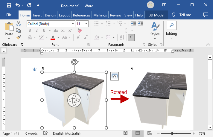
Example - Word document
In this example we have placed a corner cabinet and exported to GLB. The resulting .glb file was then placed onto a Microsoft Word document which allows you to view and rotate.
You can also double click on the file in Explorer on any recent Windows 10 or later PC, and it will open up in a 3D viewer called . And most web browsers (such as Edge and Chrome) will allow 3D viewing of a if it is placed as an image on your website.
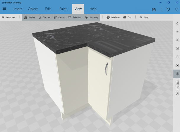
Example - 3D Builder
Click to view more details
For your clients, this file can be put on a USB drive or a file share such as OneDrive or Dropbox and given to them. They can then open it up on their home PC or Mac and rotate, pan and zoom around to view it. It is therefore really good for customers to share these files.
Clients cannot modify the file so there is no risk of your drawing getting changed but in you can change the colour of items such as benchtops and doors etc.
PhotoView allows you to generate photorealistic renders that include ultra high quality models created using -
An Environment can be included into your PhotoView render using the Use Map and Browse options. These environments are a complete 360deg background with lighting which can allow lighting to come through a window in a kitchen as well as having a full view outside.
First select Use Map and then Browse for the environment . you have downloaded. See discussion on how to locate an EXR file online.
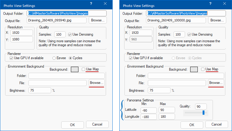
View an example of an Environment used to enhance a kitchen image
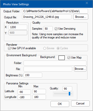
VR360 is for Virtual Reality 360 deg wrap around viewing. The process generates an image which can be viewed with a number of 3D viewers.
Looking at an image without using a 3D viewer will present a long stretchy rectangle that seems to be a distorted image. It only comes alive and looks perfect using a 3D Viewer.
Walkthrough Animation 
Watch the Video for a quick demonstration of a walkthrough available with version 12.0 [0:48 mins]
The first thing required, is that you place Cameras in 3D View at each point of interest you want the walkthrough to go through.
- See the Camera View Tutorial which discusses how to define/create each camera view to be added to the animation.
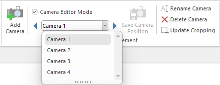
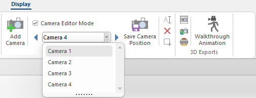
Example of Cameras added
In this example we have previously created four camera views.
Now you can press the Walkthrough Animation button to open the dialog. To create an Animation Path, select the camera views from the Camera Management List in the order you want and click on the Add Step button to add each view to the Path list.
To change order of Camera Steps use the...
-
 arrows to move selected step to 'Top' or 'Bottom' of the list, respectively.
-
 arrows to move the selected step a line 'Up' or 'Down' the list, respectively.
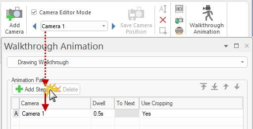
Example of Added Step
Here we have selected 'Camera 1' and then clicked on the 'Add Step' button to add to the Animation Path.
To add the next camera view, select it from the Camera Management List and repeat the process until all steps have been added.
You can also set the time it waits at each camera point and the time it takes to move between each camera point.
Walkthrough dialog options
The Walkthrough drop list allows you to create or rename an animation - click on image to view.
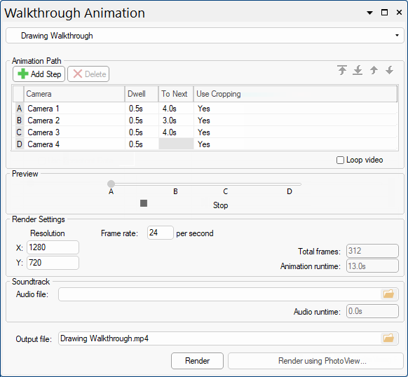
Click to view Walkthrough drop list options
You can then select the Resolution of the walkthrough you want, the number of frames per second (Frame rate) and an audio soundtrack (Audio file) if you so desire.
To create the Output file, simply press either the...
- Render button - this will use the standard CabMaster Graphics, but is the quicker option.
or
- Render using Photo View button - this uses Photo View Render and takes longer.
Calc Tool 
This command button will open the Standard Windows calculator, which can also be opened using the applicable button on your keyboard.
Video
Walkthrough Animation
Watch for a quick demonstration of a walkthrough available with version 12.0 [0:48 mins]
GLB 3D Export
A Minute with Mike : How to generate 3D GLB files to help your clients visualize their dream spaces before you turn them into reality. [1:23 mins]
Take your design visualization services to the next level!
See Also


 in the CM-Cabinets Library User Guide.