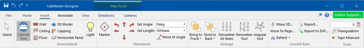
In This Topic
To locate information about any commands or tabs,  click on the area of interest on ribbon image above.
Clicking on the Select and Movement commands will direct you to a separate discussion page.
See also Drawing Tools for more information about customising object properties.
It allows you to select one (for editing) or multiple cabinets/items at the same time which allows you to copy/paste for faster reproduction of previously drawn cabinets/items.
The Keyboard Shortcut Esc returns you to the Select command if another command (e.g. Marker) or tool (e.g. Cabinet Tool) is enabled.
The Cabinet Tool is the same as that found on the Home tab, providing a quick method for inserting a cabinet from the library when the Insert tab is selected - see What is a Tool?
When you select a cabinet from a library on the Home tab, all the data for that cabinet is placed into the Cabinet Tool.
Then, provided the Cabinet Tool is active when you click on the drawing, the cabinet described by the current Cabinet Tool data is inserted at the point on the drawing where you have clicked.
All Drawing Tools have what is known as the default tool that, like a template, is usually saved in a state where the settings are as desired, so that changes don't have to made every time you use it.
This means that, when placed on a drawing, the item/object is created as a copy of the default tool. Changes can be made after placement without affecting the tool settings.
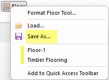
Any changes made to the default tool will be saved upon exit of the software.
If you want to keep the specifications made to an existing tool then, before making changes, use the Save As... feature (e.g. Timber Flooring), to create a tool that can be loaded in future jobs - see Creating Custom Tools.
The
Keyboard Shortcut Esc returns you to the
Select command if another
command (e.g. Marker) or
tool (e.g. Wall Tool) is enabled.
This command lets you insert walls into a drawing. Walls need to be drawn in a clockwise direction because the inside and outside faces of a wall are different (cabinets will only snap to an inside face). In general, it is best to start drawing the wall in the lower left corner of the drawing page, leaving enough space to later insert dimension lines etc.
Tip : If you hold down the Shift key, the wall will be drawn automatically at increments of 45 degrees to the starting point.
For more tips, see Wall Placement Tutorial.
There are 3 ways you can draw a wall.
- The first and quickest way is to select the Wall command and click on your starting point on your plan. Then drag the mouse in the direction and distance you want and then release the mouse button.
- The second way is to use the Movement group.
- Another option is to use the Triangulation Calculator which comes in very handy when drawing walls that were measured on site.
To end, use the Keyboard Shortcut Esc to return you to the Select command or the Wall command icon (if you want to start a new wall).
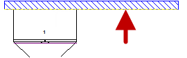
The perforated line on the wall denotes the placement side for cabinets.
Click to view Wall menu options e.g. Reverse
If your wall is not the correct way, when you try to place your cabinets, they may appear upside down.
- To correct this problem, select the wall and use Reverse from the right click menu or use the Keyboard Shortcut: S

Right click Format... opens a Walls Property Sheet.
See tutorials on Walls, Floors and Ceilings.
Ceiling 
This command lets you insert a ceiling into a drawing with options that allow it to be..
- invisible from the top, so that you can see through it when in 3D;
- it can be sloped to let you create cathedral type ceilings;
- curves and fillets are supported and tooltips provide details about the corner number and height at each point.
Example of sloped ceiling
Floor 
Floors are 'two dimensional' by default (i.e. the height is zero). Curves and fillets are supported and tooltips provide details about the corner number and height at each point.
This command makes is possible to insert a 3D Model into a drawing, enhancing your designs.
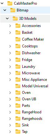
Bitmap > 3D Models folder
3D models can be any object like wineglasses, a toaster, knife rack, or anything else which cannot be constructed as a cabinet.
Models are used to add realism to the 3D view of a drawing, and many are freely available. Imported 3D Model files display their external shape in Plan View, making it easier to see what 3D Models are currently on the Plan. Each appliance cabinet has the options to display as a 'Picture' or a 'Model'.
Appliance Graphics
The Floor Dishwasher shows the difference in the display.
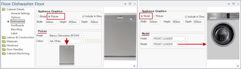
The 3D Models are stored in the Bitmap folder as shown here. ™ assumes that the models have been saved so that they are correctly positioned without the need for any rotation.
3D Models exported in the 3DS or 3DM file format can be imported into and used to create photorealistic renders.
Since some 3D Models can contain more detail than an entire drawing, they can significantly slow down movement in a 3D view if many are used. To help increase the speed in 3D, untick the 'Models' checkbox on the Display tab to temporarily hide all models in the drawing. When the viewpoint is in the desired position, reselect this option to make all the models re-appear.
You can also permanently add your imported models to the
CM-Custom-Models library. See how in the tutorial on
Adding 3D Model to Catalog.
This command lets you insert capping into a drawing.
Capping is drawn in a similar manner to a wall. To place capping into a drawing follow these steps:
- Select the Capping tool
- Click the mouse at an appropriate starting position on the screen.
- Click the mouse to place any corner points in a clockwise direction.
- This is usually easier with Snap To Handle enabled, and you can always move the corners after placement.
- When finished, turn off the capping functionality by using the Keyboard Shortcut Esc which returns you to the Select command.
This command lets you insert a Horizontal Panel (or HPanel) into a drawing.
A HPanel is drawn in a similar manner to a Poly and allows you to place horizontal sections that may form unusual shapes, which can represent items like benchtops or shelves.
To place simply select the tool and click the corner points on the plan view. You will usually want either Snap To Handle or Grid turned on while drawing HPanels. If you cross over or just incorrectly position any vertices, you can always drag them around after placement.
This command allows you to place a point light source into a drawing. Light sources can be added to create more realistic 3D renderings, acting as either light bulbs (light emitted in all directions) or spotlights (light only in a certain direction).
Up to eight lights in total can be placed per drawing (if any more than this are used they will not appear in 3D view). Lighting is only performed in 3D Solid and Textured modes. If no light sources have been added, the default "all bright" lighting will be used.
Click to place the light, which will be displayed as a "sun" icon drawn in the colour
  of the light. The effects of the light source are only visible in 3D mode, and include shadow-casting.
Markers provide a snap handle, to assist in the easy placement of other objects, and can be used if you need to set out some geometry on screen for the placement of walls, cabinets, or Paper Space objects. It not only allows you to set out precise layouts in 2D but can also be used in 3D. If you provide a height setting and go into 3D, you will see the marker at that height. This can be helpful when trying to confirm the height of things in the 3D view. See Marker Tool for an example.
Simply turn on the tool and then click on the drawing to add markers. Note that placement is made easier if you have Snap To Handle turned on.
Markers can be used to ...
- make placing a Wall easier
- leaving a gap in the wall to represent a doorway
- placing a cabinet a fixed distance from the end of the wall
- defining a bay window for which you may need to use a HPanel to represent the benchtop inside the bay window.etc
For more on this, see the Tutorial on Markers.
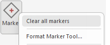
Clear all markers is available by right clicking on the Marker tool. This deletes all marker objects from the drawing, regardless of which page they are on. This command is typically used after a drawing is finished and you wish to remove any markers that were used as layout guides.
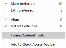
The Style default is a square but this can be changed to a diamond, plus or cross by formatting the Marker Tool.
The Movement group of commands allowing for accurate placement on the drawing and can be used in conjunction with Floors, Ceilings, Walls, Marker, and all Model Space tools - click here for a full discussion.
Extra features such as Quick Lengths and the Precise Movement dialog are also discussed in this topic.
These commands allow you to change the layering, or vertical ordering, of objects.
When two objects overlap, one will appear in front of or "above" the other. You can change which object appears in front by sending the selected object to the front or behind all objects, or in single steps forward or backward.
The vertical ordering of cabinets is not related to their physical height in 3D space. For example, a floor cabinet can be positioned on top of a wall cabinet on the page.
In plan view, objects are displayed on the drawing in the order in which you placed them. This may lead to some objects overlapping or completely obscuring others. To make an object completely visible,
select it then use the
Bring to Front command.
Takes the currently selected object and brings it forward one step. If objects placed on top of one another are considered to be in a stack, this moves the selected object one place up the stack.
To move the object all the way to the top of the stack, use the
Bring To Front command.
Similar to the Bring To Front command, except it places the selected object behind any others. For example, the floor would normally be sent to the back.
Takes the currently selected object and moves it down the stack by one position.
To move the object all the way to the bottom of the stack, use the
Send To Back command.
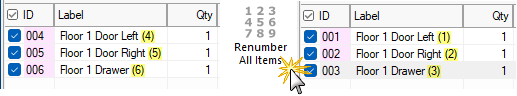
Renumber all items into the sequence cabinets were placed on the plan. These will be reflected in List View used in the following example.
To illustrate, six cabinets were place on the plan and then the first 3 were deleted. (As shown, the List View shows ID 004 to 006).
When the Renumber All Items button is clicked, the cabinets have been assigned ID's 001 to 003
 Watch the Video A Minute with Mike
 : Re-numbering Cabinets to Tidy Up Your Drawings.
Opens a dialog to allow you to manually renumber the cabinet order. This is especially helpful if you only want to change the order of the last few cabinets.
Just select a number you want to restart numbering from, then click on each of the cabinets you want to change from that number and on each click the numbers will change in sequence from that number up.
This makes it easy to set a range by cabinet type e.g. Wall cabinets all start at 200 onwards and Floor cabinets at 300 onwards. This may be helpful for easy recognition and assembly.
Watch the Video A Minute with Mike : Re-numbering Cabinets to Tidy Up Your Drawings.
Watch the Webinar which will give you an inside look at some of the speedy shortcuts and lesser-known features.
Re-orders the list of cabinets in a drawing, which can make some reports easier to read. For example, it can start from a doorway and go around the rows of cabinets clockwise until it gets back to the doorway again. It does this by drawing a line from an invisible point in the middle of the drawing to the doorway, and then swinging this line around by 360°. Cabinets are added to the list in the order that the rotating line touches them.
When you use this command it will...
- ask you to click in the centre of the plan, which will be the point around which the line will rotate;
- then you are asked to click on a gap in the drawing, which is the point where you want the sorting to start from
- when you have placed this point, the cabinets will be re-ordered.
You will not notice any change to the drawing - the only indication that anything has happened is the status bar displaying the message "Sorted". The Angular Sort function remains selected until you turn it off by clicking on the Keyboard Shortcut Esc or another command tool.
The Angular Sort does nothing to the actual position of the cabinets, it just changes the order in which they will be listed on reports.
In , the order in which you place objects in the drawing affects the way they appear in plan view. For example, if you place a floor cupboard after a wall cupboard in the same location, the floor cabinet will obscure the wall cupboard in plan view, although it is still there. This does not affect the generation of the 3D view at all.
Watch the Video A Minute with Mike : Re-numbering Cabinets to Tidy Up Your Drawings.
This command button displays a Move 3D dialog which allows you to move a cabinet a specific distance along any of its axes. You have to Select at least one cabinet/item to use this command - any other objects which are also selected will not move.
Move To Page 
This command button moves any selected cabinets and objects to a specific page of the current drawing. This command has basically the same effect as selecting the cabinets, using Cut and then Paste on the new page, except that it is faster and does not overwrite the contents of the clipboard.
If you move the objects to page zero (i.e. Common page) they will appear to not move. This is because any objects on page zero automatically appear on every other page in the drawing. Especially useful when creating templates as objects placed on page zero appear on every page. See also Using Other and Multiple Pages.
Example: If you want the certain parts of your template, such as your logo and contact details, to appear on more than one "Page" of a drawing, then you can move these to the Common Page.
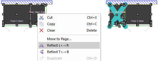
Selection from dropdown  flips the selected cabinets horizontally across the page. To flip the entire page, click Select All before reflecting.
This does not actually change the internal structure of cabinets, it just re-arranges them.
Example:
- First use select tool to select a collection of cabinets, walls etc to flip.
- Then click on the Reflect option wanted (left/right or top/bottom).
- Cabinets marked as reversible will flip, others get a big X painted on them, which means you have a placeholder for the flipped cabinet but need to replace by an appropriate one from the library.
Selection from dropdown flips the selected cabinets vertically down the page. To flip the entire page, click Select All before reflecting.
This does not actually change the internal structure of cabinets, it just re-arranges them.
Generate reports for selected cabinet i.e. invoices, cutlists etc.
Only available with and creates a machining DXF file for a selected cabinet. This file contains machining information for the selected cabinet, configured to output machining data. To create a file with all components on the drawing, refer to File > Export Machining.
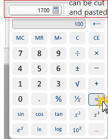
Opens the calculator application where, after clicking the equals button, numbers can be cut and pasted between the calculator and text boxes in , so you do not need to write down results and type them back in. It is a handy tool and takes up next to no space.
Pressing the  button will open the Standard Windows calculator which can also be opened using the Calc tool on the Home tab.
If you use this command and nothing happens, it most likely means that you do not have the calculator installed.
Formulas can also be entered directly into edit boxes as shown here.

The triangulation calculator is a useful tool for computing the angle of a corner, given the lengths of its edges. It is specifically designed for working out and drawing non right angled walls based on measurements taken from the field, and supports several different measurement methods.
For detailed information, see the Triangulation Calculator tutorial.
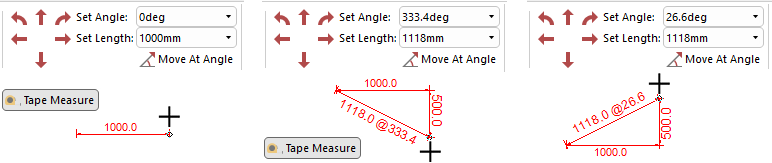
Allows you to draw a line between two points while displaying the horizontal offset, vertical offset and total distance between them. This command can also be accessed on the Annotate tab.
After selecting the Tape Measure command, click on the drawing at the first point and drag the mouse towards the second point. You will notice that as you drag, a line is drawn between the two points with the current measurements noted on it. The end points of the line are affected by snapping if you have Snap To Grid or Snap To Handle enabled.
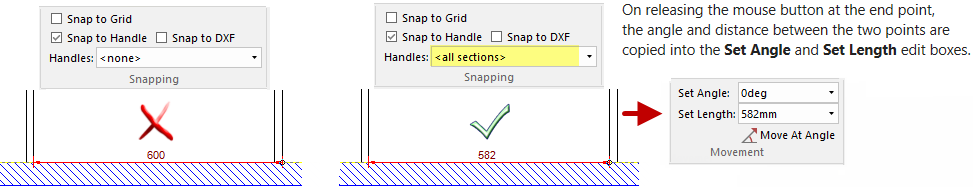
When you release the mouse button at the second point, the distance and angle between the two points are copied into the Set Length and Set Angle boxes for convenience.
Snap to Handle can also be used in conjunction with the Handles drop menu to make specific items simpler and accurate. In the example, we want to measure between the two panels but it is incorrectly measuring from a panel and a "Wall Return". Selecting "<All Sections>" provides the correct measurement.
Important: Be sure to set Handles back to "<none>" when finished.
See Also
Library Basics and Properties