CabMasterPro User Guide
One of the first things that you will want to do with a new drawing is place the walls.
There are three (3) ways to do this:-
A texture can be applied to walls to give it a more realistic appearance - see discussion on Applying Textures.
 Watch the Video which discusses placing and adjusting/formatting walls.
 on the Insert tab.
To end the wall function, click on another command icon e.g. Select.
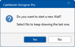
You can click on the Wall command icon to end the function. Useful if you want to start a new wall as it displays a confirmation message.
Confirmation Message
As a rule, you should draw all walls in a clockwise direction.
The Triangulation Calculator comes in very handy when drawing walls that were measured on site.CabMasterPro needs to distinguish between the interior and exterior wall surface for the correct placement of cabinets. Therefore, if you traverse wall geometry in a clockwise direction, then the interior wall surface (the surface that you will want the cabinets to align against) will be inside the room. The inside surface of the wall will show up as a dashed line in plan view, whereas the outer face is shown by a solid line.
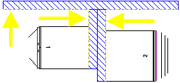
The only time this may cause any issue at all will be in the situation when you may wish to place cabinets on both sides of an internal wall as in the example shown here. The yellow perforated line is the placement side for cabinets.
If your wall is not the correct way, when you try to place your cabinets, they may appear upside down.
To correct this problem, select the wall and use Reverse from the right click menu or use the Keyboard Shortcut: S
In this example, the interior wall (actual depth = 110mm) that has Cabinets placed either side of it was drawn to a thickness of 55mm and purposefully drawn in a clockwise direction from its origin from the vertical wall. We did this to ensure that an interior wall surface would be available to place cupboards on either side of it.
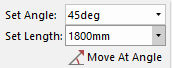
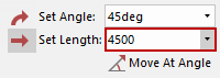
The second way is to use the Movement group of commands on the Insert tab. In this tutorial we will be creating the following...
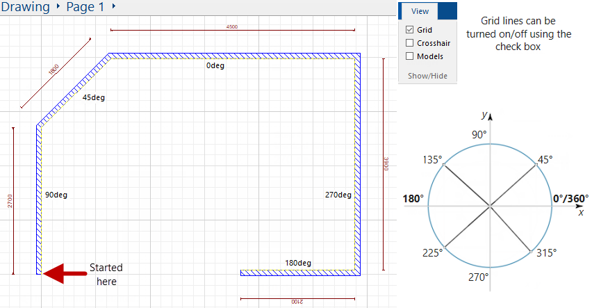
Walls need to be drawn clockwise. In general, it is best to start in the lower left corner of the drawing page, leaving enough space to later insert Dimensions, etc.
and click on the lower left corner of the drawing page to start wall - see above illustration.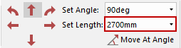
To end the wall function, click on another command icon e.g. Select.
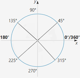
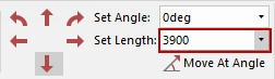
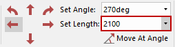
The standard angular convention is used, having zero degrees to the right, increasing in an anticlockwise direction as shown.
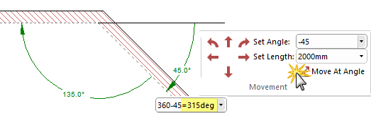
Note that adding or subtracting 360 degrees from an angle has no effect, so if you wanted to specify a distance down to the right at 30° you could either specify an angle of 330° or -30°. Using the compass we can see that an angle of 315° will provide an angle -45° (even though the internal angle is 135°).
Holding down the [Shift] key as you drag the mouse, constrains the movement direction, e.g. when drawing a wall, it not only ensures a straight wall at 0° but also allows you to draw the wall at the nearest 45° angle.
This video discusses how to place and format/adjusting walls with version 10.1 [10:14mins]