CabMasterPro User Guide
The Movement group of commands allowing for accurate placement on the drawing and can be used in conjunction with Floors, Ceilings, Walls, Marker, and all Model Space tools.
Extra features such as Quick Lengths and a Precise Movement dialog are also available and are discussed in this topic.
 |
To locate information about any part of image above,  click on the area of interest.
The Movement group of commands are located on the Insert and the Machining Editor command ribbons.
For placement of floors, ceilings and walls, by default, movement is "one way" in a clockwise direction.
To use the Movement Toolbar :
For moving at an Angle :
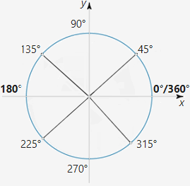
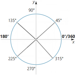
The standard angular convention is used, having zero degrees to the right, increasing in an anticlockwise direction as shown.
Note that adding or subtracting 360 degrees from an angle has no effect, so if you wanted to specify a distance down to the right at 30° you could either specify an angle of 330° or -30°.
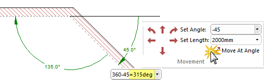
In this example, using the compass setting an angle of 315° will provide an angle -45° (even though the internal angle is 135°).
Alternatively, holding down the [Shift] key as you drag the mouse, constrains the movement direction, e.g. when drawing a wall, it not only ensures a straight wall at 0° but also allows you to draw the wall at the nearest 45° angle. You can also use the Precise Movement Input dialog (discussed below) by pressing the keyboard dot
while dragging a point/handle.
Rotation of cabinets, either single or multiple selection, can be achieved using < > keys or + - keys on your keyboard. See Rotating Items Tutorial.
To nudge an angle in 1° intervals, hold down the Ctrl key while pressing the + or - keys.
For smaller 0.1° intervals, hold down Ctrl+Shift keys while pressing the + or - keys.
Clicking on the applicable arrow command moves the mouse cursor in the selected direction by the distance specified in the Set Length box. This has the same effect as positioning the mouse at the object you placed last, moving it by an exact distance in a certain direction and then clicking the mouse button.
When you have a drawing tool from the Insert menu selecting, an object will be placed at the destination point. These commands combined with the others on the Movement menu provide a simple and accurate method of placing objects such as walls and markers.
Clicking on the applicable arrow command moves the mouse cursor along at a right angle from the angle specified in the Set Angle box.
These commands have the same effect as adding 90° (for Turn Left) or subtracting 90° (for Turn Right) from the current value of Set Angle and then using the Move at Angle command.
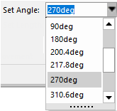 This edit box allows you to enter an angle value for use with the Move (Arrows) and Angle commands. Angles can be typed directly into the text box, or previously used values can be selected from the drop-down list. Note that you can enter full formulas into the box instead of just numerical values e.g. 360-45 (which will equal to 315°), as long as it evaluates to a number. Another simple example is to use "2.5 rad" for an angle in radians.
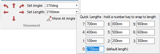
Another edit box similar to the 'Set Angle' control, except the value entered here is the distance used with the Move (Arrows), Angle, and Turn commands. The down arrow allows you to add different variables associated with numbers 0-9.
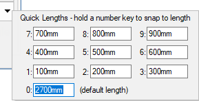
You can set 10 commonly used lengths as standards for quick use by clicking on the down arrow, as shown. These lengths can be used wherever a length can be input, such as walls, chamfers, offsets etc. You can also use complete formulas instead of simple numbers e.g. using non-default Units such as "2.34 metres".
To use a Quick Length, press the corresponding number on your keyboard while holding down the mouse button.
For example, in the image above 900mm corresponds with the number 9. Therefore, when you are begin drawing a wall that you want to be 900mm long, while holding down the mouse button, press the corresponding number down on your keyboard and it will snap the wall to that length every time you click to add another section of the wall.
Be aware that Quick Length snaps/locks to the closest 45 degrees.Watch the Video
Issue: Cabinet movement is locked to a set value.
Normally, in the plan view, you can move a cabinet freely with the mouse by dragging it around. However, sometimes the drag function will be locked to a set Quick Length value, and you cannot move it freely.
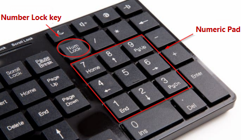
Solution: Hold down the relevant Quick Length number key on your keyboards numeric pad and then also press the Number Lock key.
Example
In this example, the cabinet is stuck only allowing 500mm movement. As per the Quick Length dialog above, this corresponds with the numeric key '5'.
To free this, hold down the 5 key on the number pad, then press the 'Num Lock' key (while still holding down the numeric key).
Watch the Video on using the Quick Lengths tool and Precision keyboard dot to Chamfer/Fillet a Corners. Moves the mouse cursor by the distance specified in the Set Length box at the angle specified in the Set Angle box. This is similar to the Move (Arrows) commands, except the direction can be set to any angle instead of being restricted to horizontal and vertical movement.
As with the Move commands, Angle has the effect of moving the mouse from its previous position and then clicking the button at the destination point. For moving along angles calculated from measurements, use the Triangulation Calculator.
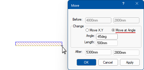
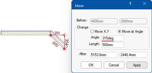
The precise movement input dialog is another way to move points - see also topic on Measurement and Placement.
Simply start dragging your selection and at the same time, press the keyboard dot once and let go.
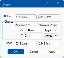
This will open the dialog where you can either Move by X,Y coordinates Left/Right/Up/Down or Move at Angle.
In the following example, we will add a section of wall at a Length of 500mm at an Angle of -45deg.
 Dimensions are automatically displayed as you manually move placed items. The colour and style can be changed by customising the Dimension Tool.

This feature in CabMasterPro is available on the Insert command ribbon.
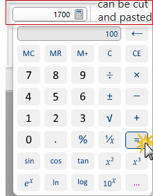
You can type directly in the edit box or click on the  to open the calculator application, as shown. When the equal sign is clicked, the result is displayed in the edit box e.g. 1700. The result can be cut and pasted between the calculator and text boxes in CabMasterPro, so you do not need to write down results and type them back in. It a handy tool and takes up next to no space.
Pressing the  button will open the Standard Windows calculator.
If you use this command and nothing happens, it most likely means that you do not have the calculator installed.
Formulas can also be entered directly into edit boxes as shown here.