Measurement and Placement
In This Topic
When you begin Part Editing, the selected part will open for editing in the main window. The Status Bar information in conjunction with the tools is used for accurate placement and measurement.
In this discussion, we will create drill holes using the Multibore tool in conjunction with an End Left part of a Floor cabinet displayed in machining view in the main window. Then we will determine:-
- the Start and End coordinates using the Model information on the Status bar;
- the distance and angle using the Dist information on the Status bar;
- What Is Delta?
- how to move points using movement tools including the Precise Movement dialog.
In this example we will discuss the
Model information in the
Status Bar.
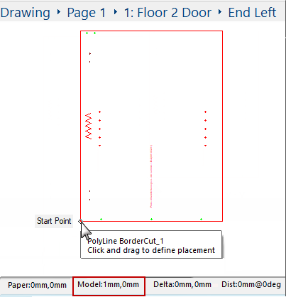
- Click on a tool - in this example the Multibore tool -
- Remember to first Unlock and you may need to double click on the tool to open the .
- Start measurement by clicking at applicable start point on the part.
- End measurement by moving/dragging your cursor to the end point on the part and releasing.
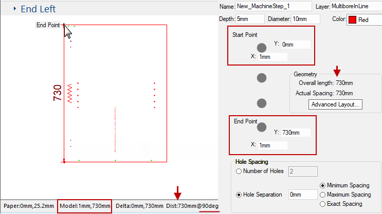
- The Model X,Y coordinate on the status bar is 1mm,730mm
- corresponds with the End Point on the
- Overall length is confirmed in the Geometry box and on the Status Bar (Dist:730mm) with additional detail of the angle i.e. 90degree (discussed next).
As the mouse moves closer to a cabinet part or item (including holes), a
Snap Diamond jumps to the closest handle.
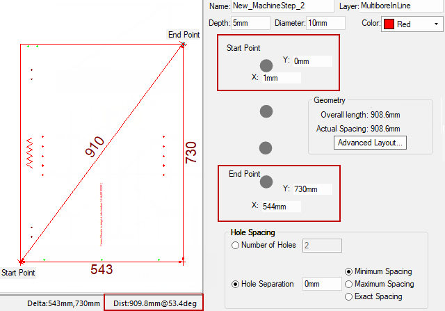
For this example, we create a diagonal line. (Click on 'Revert' to clear previous dimensioning).
- Click on a tool - in this example the Multibore tool -
- Remember to first Unlock and you may need to double click on the tool to open the .
- Start measurement by clicking at applicable start point on the part.
- The Model:X,Y coordinates on the status bar is 1mm,0mm (this caters for the 1mm edging) and corresponds with the Start Point on the .
- End measurement by again moving/dragging your cursor to the end point on the part and releasing.
- The Model:X,Y coordinates on the status bar is 544mm,730mm and corresponds with the End Point on the .
- The Distance on the status bar shows an accurate measurement of 909.8mm (confirmed in the Geometry box on the )
- The Angle is shown as 53.4deg.
Click to view more on Angle and the standard convention used
In the example above, we are measuring the part from bottom LH corner to top RH corner. The vector movement is given as a distance of 909.8mm at an angle of 53.4 degrees.
But it can also be expressed as a movement of 543mm in the X direction then 730mm in the Y direction. The X and Y movements are two sides of the right angle triangle shown and the diagonal of that triangle is the direct movement distance.
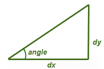
This sometimes makes it easier to view the distance you actually want to know.
For example if you have two parallel vertical lines you can click anywhere on the first, followed by anywhere on the second, and you will always get the same delta in the X direction (but different Y deltas) where the delta X is the distance between the two lines. Similarly, you can look at delta Y for the constant distance between two parallel horizontal lines.
There a number of ways to Move points but first you must click on the 'Select' command  and the Unlock
  commands.
Then you can click on hole/s you want to move and...
- Click and drag to size (relevant dimensions are displayed in real time as you move the mouse);
or
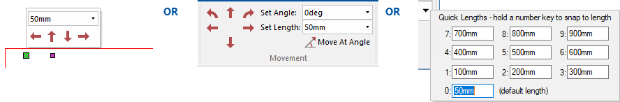
- Use the Insert > Movement tools including Quick Lengths;
or
- Precise Movement Input dialog to manually type in a dimension (open with the keyboard dot
 ).
).
Click here for discussion on the three ways to move points
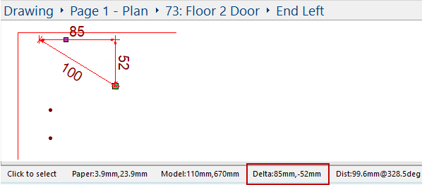
In the following the Status bar Dist shows a length of 99.6mm 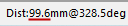 but the dimension label in the diagrams show 100.
To change the decimal display refer to tutorial on Dimensions Format Label
- One way is to click and drag using the dimensioning lines provided to accurately move your MachineStep.
- In this example, drag right 85mm and down 52mm, as verified on the Status Bar (Delta).
- Another way is to use the Movement toolbar which allows you to specify exactly where to move the points to i.e. distance and direction.
- Simply click to select the hole and you will see, as shown below left, a popup dialog.
Or
- Use the Movement commands on the ribbon, as shown below right.
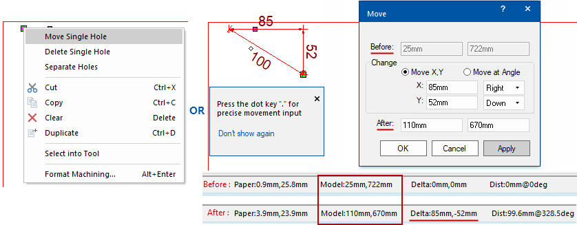
- A third way is to use the precise movement input dialog, which works almost everywhere e.g. points, poly selections, even walls on the drawing.
There are two ways that you can activate/open the dialog:-
- Simply start dragging your selection and at the same time activate it by pressing the keyboard dot once and let go (shown below right).
Or
- Select the MachineStep and use the right click menu Move Single Hole option (shown below left).
-
- The Move dialog states the Before Model X:Y coordinates and is confirmed on the Status Bar.
- Type in the exact distances to Move the selected MachineStep.
- Click 'Apply' which will show the change but not 'Save' it.
- Note that the After Model X:Y coordinates will also be stated.
- You can make more changes or 'Cancel' the movement or save the change by clicking the 'OK' button.
Video
This video tutorial discusses how to use the Quick Lengths tool and the Precision keyboard dot to chamfer or fillet the corner of a machine part. [3:02 mins]
 Watch the Video on using the Quick Lengths tool to Chamfer/Fillet a Corners.