CabMasterPro User Guide
The Machining Editor provides commands for adding new machining. The Multibore tool is used for creating a Gang of Drill Holes.
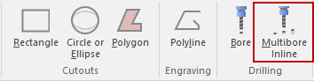
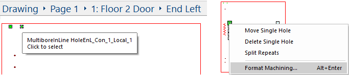
In the following example, the cursor is hovering over a Multibore Inline drill hole.
To select holes etc, you must first click on the Unlock ![]() command (grey out) and the Select command
command (grey out) and the Select command ![]() .
.
This will enable you to click and select holes or other parts displayed.
Click to select, and if the Machining Property Sheet isn't already open use the right click menu to 'Format Machining'.
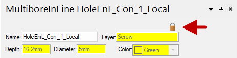
The MachineStep name, layer name, depth and diameter of the selected hole and the colour are displayed. Existing machining is formula controlled, as shown in this example. Unlock formulas by clicking on the padlock button located within the MachineStep Property Sheet. If you create your own MachineStep then this will not be necessary.
The Property Sheet for Multibore has two (2) types of layout i.e. a Simple Layout (which only displays Start and End points) and an Advanced Layout. The following example shows the difference between the two (2) layouts. Click on the button in the Geometry box to change the layout.
Any changes made in Advanced Layout that affect the Start and End points of drill holes will automatically be reflected in the Simple Layout.
The following discussion and images referred to in this topic pertains to the Advanced Layout.
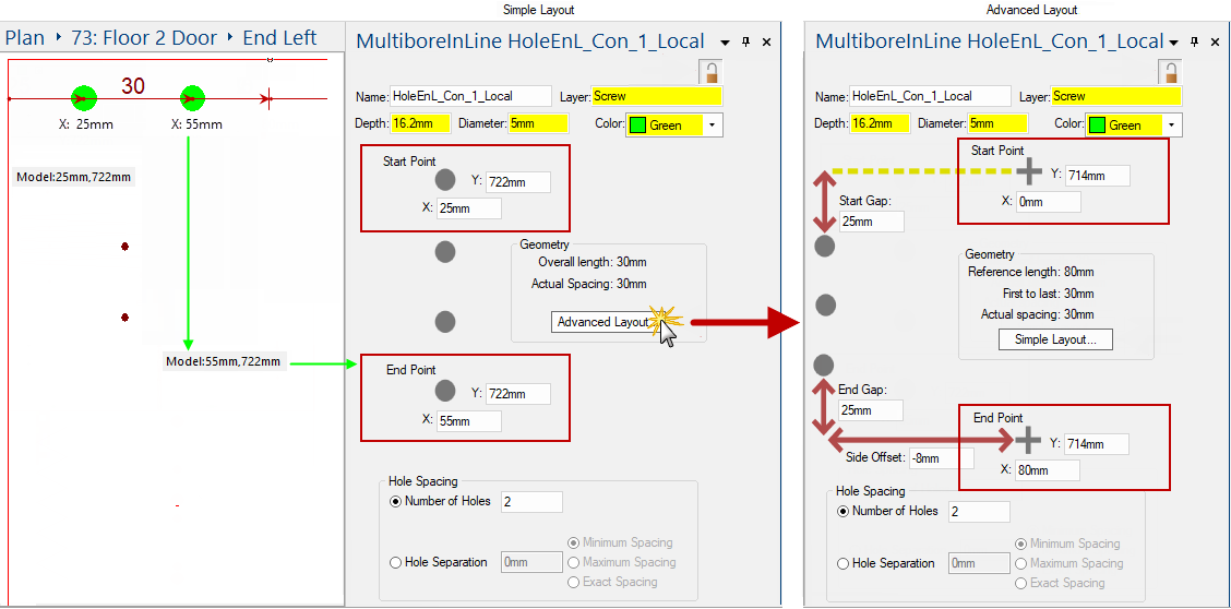
The following example shows 2 Holes as green dots. Their positions in the Advanced Layout are calculated from the reference Start Point (X:0mm) and End Point (X:80mm). [See above Advanced Layout property sheet].
Going in the direction of travel from the Start Point towards the End Point, we have specified a Start Gap of 25mm (as shown) which means the first green dot is at X=25mm. The last green dot is placed with an End Gap of 25mm as shown, so instead of placing it at the reference point with X=80mm, it is placed at X=55mm (i.e. 25mm before the "End Point").
The distance between the "Start Point" and the "End Point" is shown in the Geometry box as the Reference length, in this case 80mm as the start and end points are 80mm apart. After removing gaps of 25mm at the start and end of the reference line, we are removing 50mm of the available length, so the First to last distance is shown in the geometry box as 30mm. In this case there are only two holes and so the Actual spacing between the holes is also 30mm.
Once we set up a reference line from start point to end point, the Start Gap, End Gap and Side Offset determines the actual line from the first hole to the last hole. And usually this "First to last" available length is divided evenly to accommodate the number of holes specified.
In the following discussion, we will see that there are other options which determine the positions and spacing of the holes, but we always start with a reference line from Start Point to End Point, and an actual line after applying gaps and offsets.
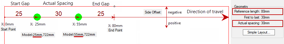
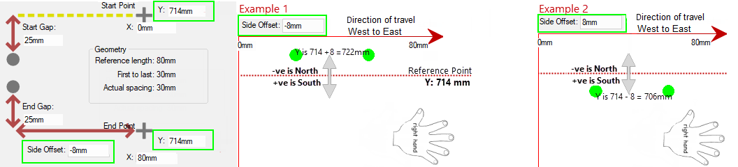
Whether the offset is a positive or a negative is determined by the direction of travel. The positive side offset direction is always to our right hand as we travel in the direction from start to finish. Here's two examples...
Example 1: Negative Side Offset travelling due East
The Property Sheet used in this example states that the Side Offset is negative 8mm (i.e.-8mm). The reference Start and End Points show that the Y values entered into the edit boxes are both 714mm (i.e. Y=714mm). Because the X values are increasing on this reference Start to Finish line (i.e. X=0mm to X=80mm), it can be determined that the direction of travel is heading due East.
Therefore, as shown below, the positive direction is to our right hand as we head East i.e. + is South. So -8 is +8mm North. So the actual Start and End points have Y=714 + 8 = 722mm. (Thus the actual holes will be drilled with centres at Y=722mm on a line going West to East i.e. 8mm north of the reference line at Y=714mm).
Example 2: Positive Side Offset travelling due East
The Side Offset specified to be added is positive 8mm (i.e.+8mm). The positive direction is again to our right hand as we head East, so the actual Start and End points have Y=714 - 8 = 706mm.
You can select Number of Holes to be evenly spaced between the Start and End Points.
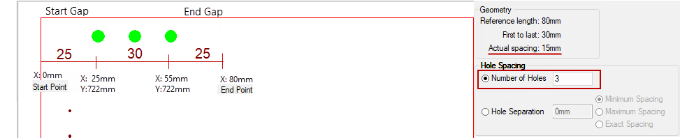
The following example shows 3 holes placed along the actual line. The reference has a Start Point of (0mm,714mm) and End Point (80mm,714mm).
The Start and End Gaps make X go from 25mm to 55mm, which is a First to last distance of 30mm as you can see in the Geometry box. The Side Offset puts the actual holes on a line from (25mm,722mm) to (55mm,722mm), adjusting the Y value from 714mm to 722mm.
Because we have specified 3 holes, the spacing is 15mm, as shown in the Geometry box as Actual spacing. Thus the three (3) holes in this example have centres at (25mm,722mm), (40mm,722mm) and (55mm,722mm).
As you can see, positioning Start and End reference points and providing Start Gap, End Gap and Side Offset and Hole Spacing information makes it very easy to accurately place rows of holes where desired.
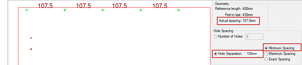
Sometimes we want to specify the hole spacing in other ways i.e. instead of dividing the available space evenly, we can use one of these three (3) options to determine hole spacing and the number of holes. In the next three examples, we have a start to end point distance (the Reference length) of 480mm and we will place holes along the actual line in three (3) different ways.
Calculation is Actual Spacing of 107.5mm x 4 = 430mm.
If we tried to drill 6 holes instead, the spacing would have to be 430mm/5 = 86mm which is too small, being under the 100mm minimum.
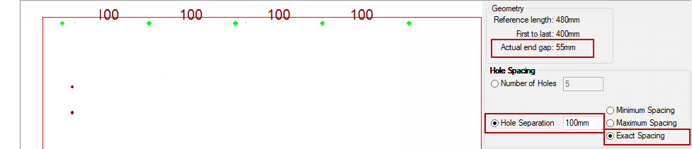
Calculation is Actual Spacing of 86mm x 5 = 430mm.
If we tried to drill 5 holes instead, the spacing would have to be 430mm/4 = 107.5mm which is too large, being over the 100mm maximum.
>
Calculation is Exact Spacing of 100mm x 4 = 400mm leaving an Actual end gap of 55mm (i.e. drilling continues until we run out of room).
The geometry box tells us that the Actual end gap is 55mm i.e. the 25mm End Gap specified, plus this additional 30mm caused by our insistence on 100mm exact spacing.