CabMasterPro User Guide
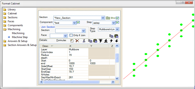
This single step has created the 18 drill holes above. The typical use of this step is to create a row of holes offset from the edge of a section, such as pilot holes for screws attaching a shaped cabinet top or bottom. In practice, you know the position of the corners (vertices) of the section and can use vertex commends to nominate those as the Start and End points. Then the MultiBoreInline step takes over and lets you control how many holes or what spacing to use, and the sideways offset and any gaps between the Start position and the first hole in the sequence and at the end between the last hole and the End point.
Here are the rules:
Now we're ready to count the holes. It measures the available space from the (adjusted) startpoint to endpoint. If the new start point and end point result in the line going in the opposite direction the step is not executed. If they are equal it drills one hole at this point.
Other than these two special events, there are four (4) ways to specify the amount of holes. Only one of these needs to be used. The first one of the fields in this list which contains a value > 0 is used and the rest are ignored:
If none of these fields are > 0 it simply drills one hole at the start and one at the end.
The above rules create a row of holes in a very controlled way, saving you from doing the maths to figure out offsets and numbers of holes.
Once you have created the sequence, you can still use RepeatCount and RepeatOffset to repeat the whole sequence. In the example above, the RepeatCount is 3 and the RepeatOffset is X=0 Y=100 so there are three rows of holes with vertical spacing 100mm, as shown in the image above.
| SecMin | The X, Y, Z co-ordinates of the min corner of the section which this machining step is inside. |
| SecMax | The X, Y, Z co-ordinates of the max corner of the section which this machining step is inside. |
| JoinMin | The X, Y, Z co-ordinates of the min corner of the section which this machining step is joined to. |
| JoinMax | The X, Y, Z co-ordinates of the max corner of the section which this machining step is joined to. |
| CutSize | X, Y, Z contain the values from this component dimcut1, dimcut2, dimcut3 respectively. |
| FinishedSize | X, Y, Z contain the values from this component dim1, dim2, dim3 respectively. |
| PartID | A name for this step, init as component name, not sent to DXF usually. |
| Layer | The layer name written to the DXF, init as steptype but you should set this to something more meaningful e.g. in EzyNest. In addition, this layer value can be prefixed by + - or ~. The prefix is not sent to the DXF, but is used to indicate notches, where two steps are combined. A + is for combining two steps by adding the paths together. This can extend the outer shape. A - is used for subtracting or creating a notch. And a ~ is for flap donor steps. (See Flaps In Remote Components) |
| Group | The group name written to the DXF. Default value is ungrouped. Different groups will be nested separately, so for example a DXF with some ungrouped machine steps and some steps in group 10 and others in group 20 will nest as three separate parts. |
| ColorIndex | The color used in the DXF (usually unused by Machining but very helpful for viewing). Colors are defined by Voloview DXF viewer. (See also DXF Layer Colours):
|
| Radius | Radius of hole. |
| Depth | Depth of the of the cut/drill. |
| Start | XYZ: location of start of the machining step. |
| End | XYZ: location of end of the machining step. |
| SideOffset |
See Machining Editing > MultiBore Inline explanation.
|
| LongOffset | Shifts the placement points in the start to end direction (ie longitudinally). Setting LongOffset to zero or empty will leave the points where they were. |
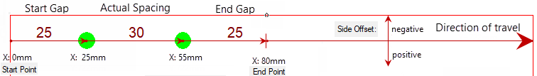
| StartGap | See diagram above and discussion on Machining Editing > MultiBore Inline. |
| EndGap | See diagram above and discussion on Machining Editing > MultiBore Inline. |
| NHoles |
Used as one of the machinestep entry names, and refers to the intended number of holes in that specific machinestep. The actual number of holes drilled will depend on the part dimension as some holes may not fit on the part. Also there could be repeats in this one machinestep e.g. a column of shelf holes near the front of the shelves and a repeat to give a similar column of holes near the back. Furthermore, sometimes the actual number of holes drilled is determined more by the spacing between holes. So NHoles for one machinestep is an important variable but the actual number of holes drilled could even be different on two parts with the same machinestep definition, if the overall part dimensions are different - See Machining Editing > MultiBore Inline explanation. |
| SepMaxMinExact | See Counting Holes above. |
| StartDrillingSlowdown | Field not yet implemented. |
| EndDrillingSlowdown | Field not yet implemented. |
| RotationDirection | Field not yet implemented. |
| RotationSpeed | Field not yet implemented. |
| DrillingSpecial | Field not yet implemented. |
| RepeatCount | X: Whole machine step is repeated this many times. Y: If this is >1, then do a rectangular array of repeats. |
| RepeatOffset |
XY: Offset vector between copies (for linear repeats). For arrays of repeats, X is the X offset and Y is the Y offset. Example Here is a little example of a BorderDeco step repeated in a 3x2 array:
|
| ProfileFolder | Folder for QPFs, default BitmapFolder, can be relative. |
| ProfileName | Name of the profile. The default extension is ".qpf". An array of names is allowed, if defining multiple profile edging. |
| ProfileEdging | Array of edge treatments. See Edge and Pocket Profile Tutorial : Defining a Profile |
|
Entry is a yes/no determining whether the area inside the machinestep is to be removed. Applies to contours (closed polylines only). | |
| FeedSpeed | Field not yet implemented. |
| Face | Face=0 normally, other faces used for side boring. 1=Left, 2=Bottom, 3=Right, 4=Top edge. |
| Pitch | Field not yet implemented. |
| EntrySpeed | Field not yet implemented. |
| Offset | Field not yet implemented. |
| OffsetAmount | Field not yet implemented. |
| ToolDiameter | Field not yet implemented. |
| ToolNumber | Field not yet implemented. |
| ToolType | Field not yet implemented. |
| RunField | Field not yet implemented. |