CabMasterPro User Guide
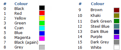
All machining layers can have their DXF layer colours customised. The DXF layer colour (a whole number).
The color used in the DXF is used for visability within CabMasterPro, not by the machining software. When DXF files are created in the design applications, different types of machining operations are separated onto different layers in the DXF files. The geometry on all the Layers in a file represents a single part, and all the machining such as drilling, milling and cutting, that is to be performed on that part.
The Layers table is editable from the Catalog\Drawing properties on the Mach.General > Tool page  . One reason why you may like to change a colour is that 'veins' denoted by yellow are sometimes hard to see.
These are also referred to as the Color Index.
Click to view Bitmap folder
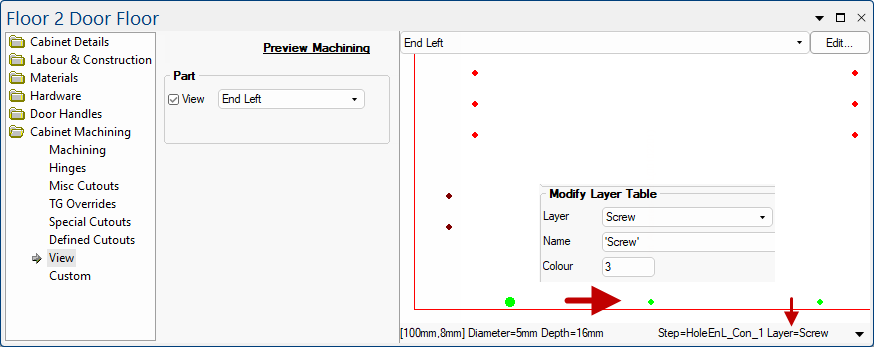
In these examples we have used a Floor cabinet. In machining view the slider is replaced by the status bar the bottom section of the Preview Pane.
In the first example, we have clicked on the one of the green dots and the preview states that it represents a Layer=Screw and provides the step name of the selected machining for each layer used.
Click to view Mach.General > Tool page
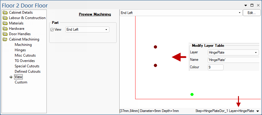
In the second example, we have clicked on the one of the brown dots and the preview states that it represents a Layer=Hinge Plate.
By clicking on the a machine step, the status bar, opened in the main window or preview pane, will provide the following details...
Click to view Mach.General > Tool page