CabMasterPro User Guide
Allows spec of the shape of each hole or tab of multiple holes offset from the center along a line between two points i.e. makes a copy of the shape at each “inline” point on its start-to-end line.
Example
When you count the notches/tabs, it measures the available space from the (adjusted) startpoint to endpoint. If the new start point and end point result in the line going in the opposite direction, the step is not executed. If they are equal, it adds a notch/tab at this point.
This controlled way of adding notches/tabs, saves you from doing the maths to figure out offsets and numbers of notches/tabs.
Once you have created the sequence, you can still use RepeatCount and RepeatOffset to repeat the whole sequence.
| SecMin | The X, Y, Z co-ordinates of the min corner of the section which this machining step is inside. |
| SecMax | The X, Y, Z co-ordinates of the max corner of the section which this machining step is inside. |
| JoinMin | The X, Y, Z co-ordinates of the min corner of the section which this machining step is joined to. |
| JoinMax | The X, Y, Z co-ordinates of the max corner of the section which this machining step is joined to. |
| CutSize | X, Y, Z contain the values from this component dimcut1, dimcut2, dimcut3 respectively. |
| FinishedSize | X, Y, Z contain the values from this component dim1, dim2, dim3 respectively. |
| PartID | A name for this step, init as component name, not sent to DXF usually. |
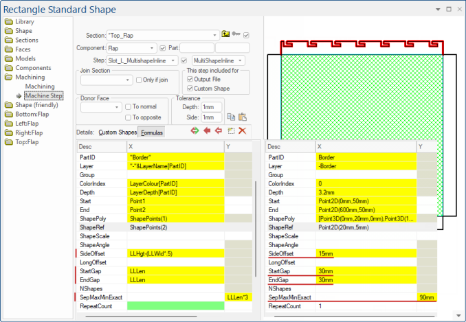
| Layer |
Layer overrides any layer specified in the ShapePoly machinestep, so you can use the same shape both for a tab and a notch, perhaps with slightly different scales to provide a gap. X contains Layername (e.g. -Border) The layer name written to the DXF, init as steptype but you should set this to something more meaningful e.g. in EzyNest. In addition, this layer value can be prefixed by + - or ~. The prefix is not sent to the DXF, but is used to indicate notches, where two steps are combined. A + is for combining two steps by adding the paths together. This can extend the outer shape. A - is used for subtracting or creating a notch. And a ~ is for flap donor steps. (See Flaps In Remote Components) |
| Group | The group name written to the DXF. Default value is ungrouped. Different groups will be nested separately, so for example a DXF with some ungrouped machine steps and some steps in group 10 and others in group 20 will nest as three separate parts. |
| ColorIndex | The color used in the DXF (usually unused by Machining but very helpful for viewing). Colors are defined by Voloview DXF viewer. (See also DXF Layer Colours):
|
| Depth |
Depth overrides any depth specified in the ShapePoly machinestep. This is the depth of the notch or tab. You can also use Refz to offset the shape up and down (not implemented yet). X contains Length (e.g. 16mm). See Specifying the PolyShape MachineSteps. |
| Start | XYZ: location of start of the machining step. |
| End | XYZ: location of end of the machining step. |
| ShapePoly | Defines the poly to be used, either once or repeatedly. X contains Poly/PolyArc array. See Specifying the PolyShape MachineSteps. |
| ShapeRef | XYZ: Gives (Refx,Refy) in the same coordinate system as the shape poly. See Specifying the PolyShape MachineSteps. |
| ShapeScale |
XY: Used to scale with the reference point as the centre of the scaling. Example (Sx,Sy) is (-0.1,0.1) See Specifying the PolyShape MachineSteps. The x-values of points in the ShapePoly are stretched by a factor Sx, and the y-values by the factor Sy. |
| ShapeAngle |
Applied to rotate the scaled shape around the reference point by the angle provided, where counterclockwise rotations are positive. X contains the Angle. |
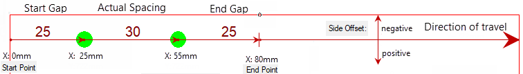
| SideOffset | Whether the offset is a positive or a negative is determined by the direction of travel. The positive side offset direction is always to our right hand as we travel in the direction from start to finish. See diagram below. |
| LongOffset | Shifts the placement points in the start to end direction (ie longitudinally). This applies to both MultiboreInline and MultiShapeInline. Setting LongOffset to zero or empty will leave the points where they were. See Machining Editing > MultiBore Inline explanation. |
| StartGap |
See Machining Editing > MultiBore Inline explanation. |
| EndGap | See Machining Editing > MultiBore Inline explanation. |
| NShape |
Used as one of the machinestep entry names, and refers to the intended number of notches/tabs in that specific machinestep. The actual number of notches/tabs will depend on the part dimension as some notches/tabs may not fit on the part. Also there could be repeats in this one machinestep. Furthermore, sometimes the actual number of notches/tabs is determined more by the spacing between notches/tabs. |
| SepMaxMinExact | See Counting Shapes above. |
| RepeatCount | X: Whole machine step is repeated this many times. Y: If this is >1, then do a rectangular array of repeats. |
| RepeatOffset |
XY: Offset vector between copies (for linear repeats). For arrays of repeats, X is the X offset and Y is the Y offset. Example Here is a little example of a BorderDeco step repeated in a 3x2 array:
|
| ProfileFolder | Folder for QPFs, default BitmapFolder, can be relative. |
| ProfileName | Name of the profile. The default extension is ".qpf". An array of names is allowed, if defining multiple profile edging. |
| ProfileEdging | Array of edge treatments. See Edge and Pocket Profile Tutorial : Defining a Profile |
|
Entry is a yes/no determining whether the area inside the machinestep is to be removed. Applies to contours (closed polylines only). |