CabMasterPro User Guide
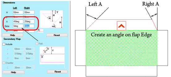
When there is a need to add either a cutout notch or a shaped tab to the edge of a panel, there are three machinestep types that allow you to configure the shape of the notch or tab, and also scale, orient and position it.
These three machinestep types are...
PolyShape Similar to Bore, but allows you to specify the shape of the hole or tab.
MultiShape Similar to MultiBore, but allows you to specify the shape of each hole or tab.
MultiShapeInline Similar to MultiBoreInline but allows spec of the shape of each hole or tab.
These machinesteps provide a layer and a depth, in the usual way. However the layer is prefixed by a ‘-‘ or ‘+’ character. The minus character indicates this is a notch (i.e. a shaped hole). The plus character indicates this is a shaped tab.
The ShapeScale is specified as a pair of numbers (sx,sy). Making these numbers both 1 will just copy the polyshape without changing its scale. Making sx and sy different will distort the shape, stretching it in the x or y direction. The numbers can also be negative, and that will flip the shape in the x or y direction, or both.
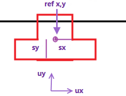
The shape itself is always defined as a closed poly Point1, Point2, Point3, … etc. And the points have length coordinates in the usual x and y directions (shown in the diagram as ux,uy).
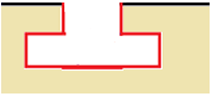
In this example, the shape (in red) will be positioned near the edge of the panel (shown in black). If the PolyShape above is put into the same layer as the black edge but with a ‘-‘ prefix, it will combine with the edge to form a notch, like this:
In the diagram, we show the reference point (refx,refy). The PolyShape will be positioned so that this reference point is exactly at the “point” we define in the PolyShape.
Often the poly or polyarc providing the points of the poly shape is from another machinestep. Or it can be directly defined as an array of points with optional arc radiuses if it’s a polyarc. Below we’ll discuss the multiple ways these poly or polyarcs can be defined. They can be setup in another machinestep, or directly defined as an array of points and optional radiuses.
Making sx, sy both 1 will just copy the shape without changing the scale. Making sx negative will flip the shape left/right, ie in the x direction. The points of the poly may be 10 times the size we actually want them to be in the final PolyShape. In that case, we would specify sx and sy to both be 0.1, and all lengths would be multiplied by 0.1, which scales the shape down by a factor ten. The reference point is the central point for this scaling. So (refx,refy) remains in the same place. But a point 100mm to the right of the reference point would end up just 10mm to the right if sx is 0.1. Similarly, a point 100mm upwards in the uy direction above refy would end up just 10mm above that point.
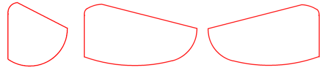
Scales sx and sy are usually the same, and arc radiuses are also scaled by that amount to ensure that a polyarc looks the same, just scaled up or down in size. But sx and sy can be different. For example, sx = 2 and sy = 1 would just stretch the shape in the ux direction. And in that case, the arcs of a polyarc shape would be automatically converted into a pair of arcs, ensuring that the tangents match the original directions smoothly at the start and end of the curved shape. Here’s an example…
The original polyarc on the left is placed with sx and sy as 1. The arcs each have a single radius. The second one is the same polyarc with sx = 2 and sy = 1. Now each curve is split into a two arc fit. The good thing about “two arc” fitted curves is they can still be easily sent to a CNC machine for cutting as each curve now just requires a pair of G2 or G3 arc routes.
Scales can also be set negative, causing a shape to flip. The third example has sx = -2, sy =1. So it is just like the second one, but flipped in the ux direction.
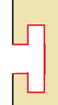
After scaling a shape it can also be rotated about the reference point. For the example above, the shape is being placed without any rotation. This would be done by leaving the “ShapeAngle” as zero. But if you wanted to add this notch to the left end of the panel, it can be rotated by specifying an angle of 90 degrees, giving this result:
The ShapeAngle specifies the amount of CCW (counter clockwise) rotation to apply to the poly when adding it in as a PolyShape.
Poly and polyarc shapes can be defined directly as arrays, or can be pulled from another machinestep easily.
When defining a poly with no arcs, we can just list the points in an array like this…
[Point2D(-10mm,-10mm), Point2D(10mm,-10mm), Point2D(10mm,10mm), Point2D(-10mm,10mm)]
...or another equivalent shorthand way of writing this same array is this...
Point2D([ [-10mm,-10mm], [ 10mm,-10mm], [ 10mm,10mm] , [ -10mm,10mm] ])
If it is a polyarc, this means some edge of the poly has a radius. So instead of providing an array of Point2D values, you need to provide an array where each element of the array is a map like this
{ “p”: Point2D(-10mm,10mm), “r”: 2.83mm }
So the whole array is the list of these little maps… [ map1, map2, map3 ].
For both poly and polyarc data, we can also provide the data by referencing another machinestep with .poly like this
MachineStep[“Complex”].poly
The machinestep can be any other machinestep which contains a poly or polyarc. Examples are Border, BorderArch, PolyArc and so on. The step does not have to be active – just defined. That is, its IsPresent checkbox can be turned off.
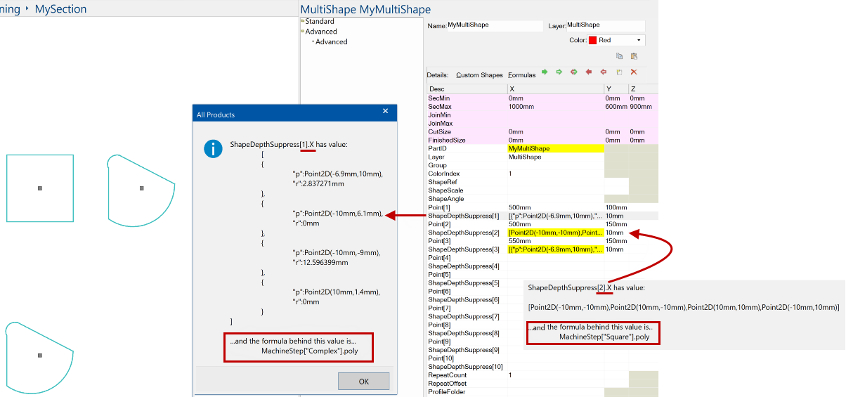
In the following image, we use a MultiShape machinestep called MyMultiShape. Notice that each shape is defined using a formula (in red) MachineStep[“xxx”].poly.
Allows you to specify a single shape. Of course you can still use repeat counts and machinestep sequences to turn it into a set of polys.
Allows you to specify a list of shapes, specifying each one’s centre point and shape, rather like we specify a multibore as a sequence of individual drill holes. In this case, there is always just one ShapeAngle and ShapeScale sx,sy scalefactors, used for all the shapes.
The list of ‘shapes’ is defined similarly to Multibore which defines a list of ‘drill-holes’. Where Multibore has pairs of lines like Point[1], RadiusDepthSuppress[1] etc, MultiShape has pairs of lines like Point[1], ShapeDepthSuppress[1] etc. The first shape is specified by ShapeDepthSupress[1].x, and is a poly or a polyarc. Each shape can be a different poly, and a different depth, but all shapes in the list have the same ShapeAngle orientation and ShapeScale scale factors sx,sy.
Allows you to position a row of shapes, all at the same orientation and scale factor. This uses the positioning method of the MultiBoreInline machine step, though, to make it easier to position multiple shapes. And it also makes it easier to determine the desired orientation angle – by default this angle is set to match the direction from the start point to the finish point of the step specification. This start to finish line is used to align the x-axis ux in our first diagram above. But we still can specify an extra ShapeAngle which rotates the shape further.
Here’s an example showing the MultiShapeInline machine step. We start by showing a MultiBoreInline, where we define a row of 6 holes along the line “start→end” with the specified “sideoffset”:
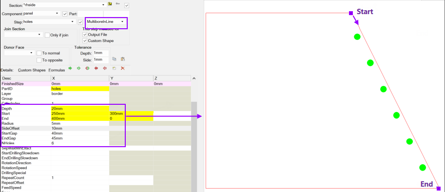
For the MultiboreInline the holes are always circular, with the “Radius” as specified. MultiShapeInline lets us specify a row of notches or tabs, where the shape of each one is defined by the poly in the reference machinestep. That is, instead of only having circular holes, you can now have holes (or tabs) with shapes defined by a poly specified directly or in another machinestep.
The poly shape scaled and rotated, then repeated once for each multiboreinline “hole”, with its reference point positioned where the centre of each multibore inline hole would be. So using the earlier example shape above, here’s how the first of these holes might look…
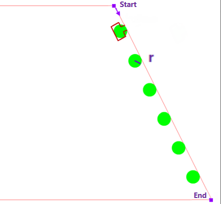
The green circles (the original holes) are no longer there and will each be replaced by the red poly shapes as shown. As well as positioning the (refx,refy) points at the centres of the green circles, it rotates the poly so its x-axis (ux) points in the direction of the multiboreinline x-axis, shown above as ux.
Note: For added flexibility, as well as SideOffset there is now a LongOffset that shifts the placement points in the start to end direction (ie longitudinally). This applies to both MultiboreInline and MultiShapeInline. Setting LongOffset to zero or empty will leave the points where they were.
During placement the polyshape is scaled in the x and y directions, as discussed for the PolyShape step above. So everything in the red poly is scaled so that for any edge in the original x direction, its length is scaled by the factor sx specified in ShapeScale.x and any edge in the original y direction is scaled by ShapeScale.y.
Remember, we can also make sx or sy or both negative if we want to flip the shape.
Everything is scaled relative to the (refx,refy) reference point. So in general, a point (px,py) of the poly will be scaled to (qx,qy) like this…
qx = refx + (px – refx) * sx
qy = refy + (py – refy) * sy
Notice that when sx = sy = 1, the point (px,py) will just give the same point (qx,qy). Whereas if sx = sy is 10 then everything in the notch poly will grow by a factor 10.
If you change sx to a negative number it will flip the shape about the ref point in the x direction.
If you change sy to a negative number it will flip the shape about the ref point in the y direction.
And once you have a scaled shape (refx,refy) will be placed at the “hole centre” and the shape will be rotated so that its x-axis is along the direction of the multishapeinline axis, from start towards finish.
Aside from the usual geometry information, which depends on which of the machinestep types you are using, we need to provide these machinestep entry rows in the grid:
| Name | X | Y | Z | Example | Comments |
| Layer | Layername | -Border |
Layer overrides any layer specified in the ShapePoly | ||
| Depth | Length | 16mm |
Depth overrides any depth specified in the ShapePoly | ||
| ShapePoly | Poly / polyarc array | MachineStep["a"].poly |
ShapePoly is the machinestep defining the poly to be used, | ||
| ShapeRef | Refx | Refy | Refz | (100mm,50mm) |
ShapeRef gives (Refx,Refy) in the same coordinate system |
| ShapeScale | Sx | Sy | (-0.1,0.1) |
ShapeScale is then used to scale with the reference point In the example above, Sx is -0.1 so the x-values are flipped in | |
| ShapeAngle | Angle | 90deg |
ShapeAngle is then applied to rotate the scaled shape around |
ShapePoly could be a PolyArc machinestep, or a BorderArch or BorderDeco all closed poly machinesteps are supported for providing notches and tabs.
Use the link here to download the sample drawing (.qid) that the following notes refer to. Open with no library selected i.e. <none>.
This ShapeWSlots PolyShape 202409.qid will not open correctly without a ShapeMasterV12 installation (and Library v12.000.2.1 at least) but the PolyShape applies to all CabMaster Software™ products.
In these example, we have four flaps, each have a different setup to look at the different methods of creating a polyshape with slots.
Essentially it mimics the Bore, Mutibore, MultiboreInline but instead of drilling the holes, in each position where a hole would be drilled we are going to be able to put a shape, described as a PolyShape. These polys are generally obtained from another machine step - it looks for a machinestep that has a poly or a direct specification of a poly e.g. borderarch or any polyarch steps etc. Then you can reference that machinestep and say .poly and it will deliver the sequence of points.
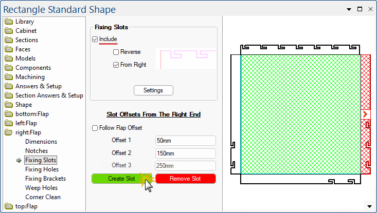
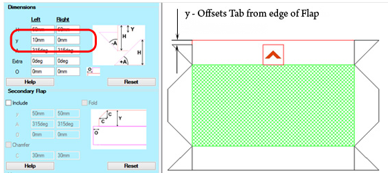
The Right flap is the standard machining with 2 slots added using the "Fixing Slots" friendly page.
The Bottom flap again has slot offsets defined by the friendly page, but the "Include" check box is left unticked.
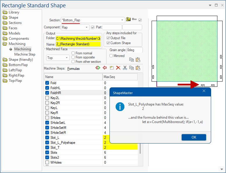
The slots are then implemented using a PolyShape machine step called "Slot_L_Polyshape". This looks up the poly and reference points from the existing middle ware and positions them appropriately. Multiple slots are achieved by setting up MaxSeq, each Seq corresponds to a slot position.
Bottom Flap : Slot_L_Polyshape
Click on image to view the Machine Step Slot_L_Polyshape.
Click to view Machine Step
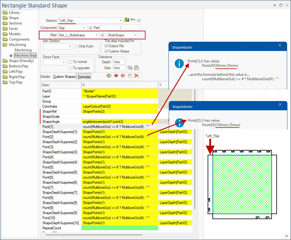
The Left flap similarly implements the slots using a MultiShape machine step called "Slot_L_Multishape". Here we do not need a MaxSeq definition because the shape reference points are set up as Point[1],Point[2] etc.
MultiShape and Slot_L_Multishape
This is a single machine step.
Click to view alternative PolyArc Machine Step
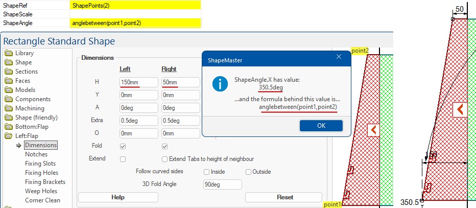
MultiShape and ShapeAngle
In this example we are demonstrating the ShapeAngle where Point 1 is the bottom left corner and Point 2 is the top left corner.
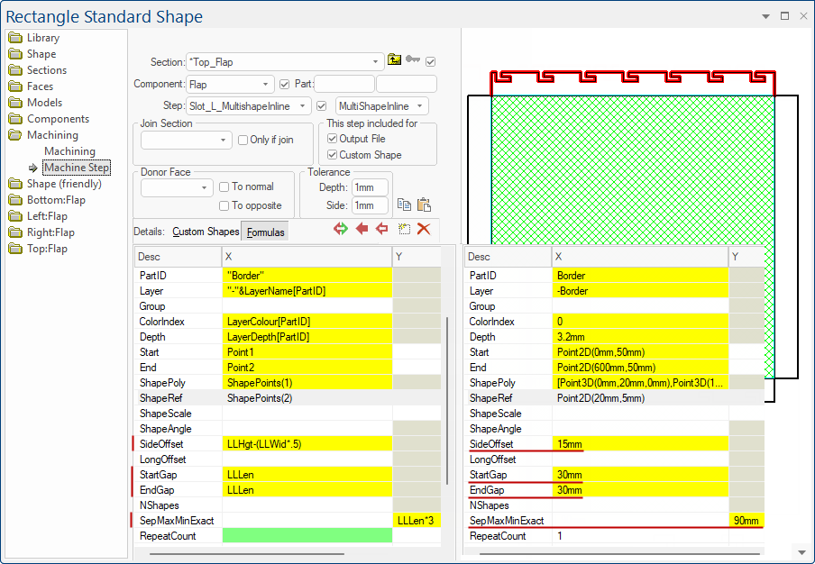
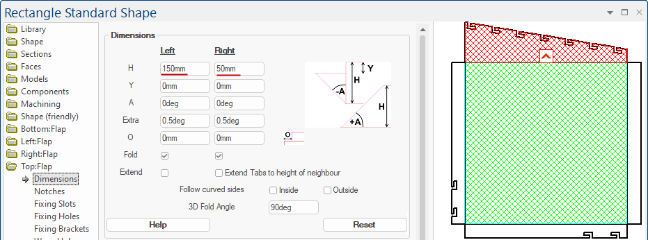
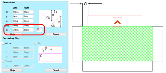
The Top flap does not use the friendly page slot offsets at all, but instead, demonstrates a MultiShapeInline step to create evenly space slots ["Slot_L_MultishapeInline"]. This uses the edge reference points as Start and End, picks up the poly and then lays out the reference points using the StartGap, EndGap, SideOffset and SepMaxMinExact.
MultiShapeInline and Slot_L_MultishapeInline
In many ways, is a simpler concept. The LongOffset gives you flexibility as it shifts the placement points in the start to end direction (i.e. longitudinally). This applies to both MultiboreInline and MultiShapeInline. (Setting LongOffset to zero or empty, as shown here, will leave the points where they were).
The reason that you may want to do this in a separate way is because, as you place these slots in polys that can have unusual shapes, you are always placing them at a reference point. You don't have unlimited flexibility in defining where you choose this reference point to be e.g. when you are defining the shape of the slot, you may need to scale and/or rotate.
Angled Flaps with Slots Rotated
When you set the flap at an angle, the slots are automatically rotated, as shown.