CabMasterPro User Guide
|
|
For quick links to more information, click on  the options or another page.
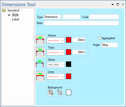
The Dimensions Tool Classic has been added in v12.1 and will make formatting text simpler. See also Tutorial on Dimensions.
 Watch the Video below, which discusses how to use both the v12.1 Dimensions Tool Classic (shown above right) and the legacy DimensionV10 options.
This drawing tool is located on the Annotate tab can be customised with the right click Format... option.
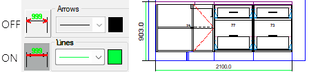
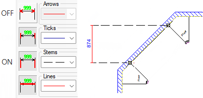
The buttons, shown below left, are used to Include or Exclude the Arrows, Ticks, Stems and/or Lines. The example shows Arrows turned off.
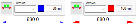
This set of controls is used to specify and display arrows on the end of dimension lines. The icon button on the left shows a dimension line with the arrows highlighted to indicate that it is used to turn arrows on and off.
Next to this, there is a drop list for selecting the line thickness and style for arrowheads. Clicking the coloured square will open a standard Color Select dialog where you can select the colour to draw dimension arrows with.
Finally, the edit box on the right sets the length of the arrow heads which is in real-world dimensions, so a typical value may be 50mm.
These controls let you specify the length, colour and style of the lines which are drawn at each end of a dimension. They are the same as those for the arrowheads, so you can turn them on and off using the button icon on the left and so on.
The Slashes (architectural style) controls let you specify the length, colour and style of the slashes and the degree of slant of the slashes drawn at each end of a dimension.
You can turn them on and off using the button icon on the left and so on.

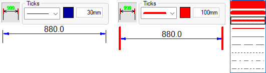
As with the arrows and ticks, these controls are used for setting the colour and style of the stem lines. These are the lines which extend from the ticks to the object being dimensioned, and are typically drawn with a lighter dashed line style.
This option is a compact version of the Transparency and Back Color controls from the common Line page. These controls are only available when the selected Line Style has gaps in it e.g. a crosshatch fill pattern or a dashed line, as per the example below.
When one of these patterns is used you can set the transparency option to either transparent or opaque ![]() respectively. When transparent is selected, anything behind the object shows through the gaps.
respectively. When transparent is selected, anything behind the object shows through the gaps.
With opaque, everything behind the object is obscured and the object's background colour is drawn in the gaps instead. In this example, the blue back colour is visible between the red line colour.
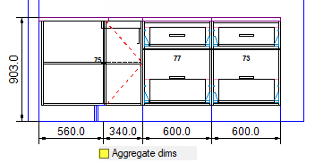
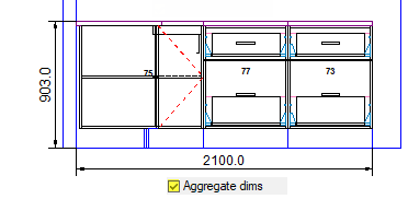
A dimension line usually shows, below left turned OFF, the width of each cabinet that is measured by the dimension, but sometimes you might wish to display only the total length of the line instead, shown below right turned ON.
Turning ON 'Aggregated' means the dimension line will not be broken up into multiple measurements but will collect all the lengths into a single dimension. Any sub-dimensions which disappear when you tick the 'Aggregated' check box are only hidden, not deleted, so unticking it will show all the individual measurements again.
This is the angle that the dimension line is drawn along. By default, a dimension starts off with an angle parallel to the edge it is measuring, but you can set it to any angle you like. The length that the dimension measures is along its own dimension line, so when you change the angle of a dimension, its length will change even though the edge stayed the same.
When a dimension in placed that the angle will be set to the value on the Style page, and may not be parallel with the wall or cabinet. You can change this value if required.
Be aware that the angle field on the Label page is relative to the angle of the line, it is not an absolute angle. So setting this to zero degrees will always print text along the line.
The Dimensions Tool Classic has been added in v12.1 and will make formatting text simpler.
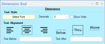
On every dimension line you use, a label is placed along it showing details about that line/angle/leader. These labels can show a range of different items such as units, decimals, notations etc.

Click to view examples of Text Style
The Select Font button opens the standard Windows Font dialog, where you can set the typeface, point size, style, effects and colour of the text. There is a sample area on the font dialog where you can see how the selected options will affect the text appearance. When you close the dialog, the text updates to reflect the selected font and is visible on the drawing page.
Dimensions use this edit box to show a range of different items such as units, decimals, notations - see Format String Examples below.

The Justification buttons control where the text of a label appears horizontally relative to its attachment point. Unlike the Style buttons, these are linked so you can only select one at a time. From left to right, the buttons select left, centre and right justification, just like in any word processing application. With a Label, this only shifts the text left and right.

The Alignment of a label is similar to the justification, except it controls the vertical position relative to the attachment point.
The three buttons Below, Thru and Above are linked so you can only select one at a time.
This is the angle that the text appears at on the drawing, with normal horizontal text being at zero degrees. You can enter any angle in either degrees or radians, and the text will be rotated around its attachment point by that angle.
| Result | Format Used | Comment | Notes |
|---|---|---|---|
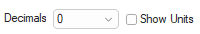 |
No format used (default) | With the default precision and no units shown | |
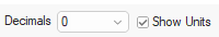 |
no decimals, hide units | Since precision was specified as "no decimal places", note that the number has been rounded, not just cut off. | |
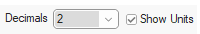 |
2 decimal places, show units | Shows the current units being added to the label with 2 decimal places. | |
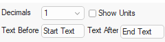 |
custom text before and after format |
Shows that you can still have other text in a dimension label. The text is printed as it appears, except the format string is replaced with the dimension length. The format string is only replaced once, and if no format string is explicitly included it is appended at the front of the label. |
A Minute with Mike : This video discusses the difference between the V12.1 Dimensions Tool Classic and the legacy DimensionsV10 options.