In This Topic
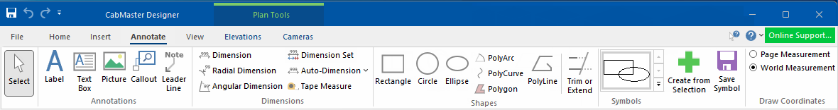
To locate information about any commands or tabs,  click on the area of interest on ribbon image above.
See also Drawing Tools for more information about customising tool properties.
The
Keyboard Shortcut Esc returns you to the
Select command if another
command (
e.g. Dimensions) or
tool (
e.g. Cabinet Tool) is enabled.
It allows you to select one (for editing) or multiple cabinets/items at the same time which allows you to copy/paste for faster reproduction of previously drawn cabinets/items.
Annotations are drawing tools, allowing you to add a note, comment,explanation or a picture to your drawing.
For more on how to use these drawing tools, see the Annotations Tutorial.
This command lets you place text into a drawing.
Watch the Video A Minute with Mike on Utilising the Label Tool for Annotations.
This is especially useful when creating templates using supplied variables (see topic on how to Load Variables).

Right click Format... opens a Labels Property Sheet.
It allows you to customise text, font style, alignment, angle, and other effects.
This command lets you insert text inside a rectangular box into a drawing. The text auto-wraps to fit inside the box, and if there is too much text, it is .
To place a text box on a drawing, you need to specify two points which are opposing corners of the rectangle. Just select the text box tool, click on the drawing while holding the button down, then drag the mouse to form a rectangle. You can then move the text box and resize it exactly to your needs.
This command lets you insert a picture directly into a drawing. can be created, viewed, and edited in 'Paint', which comes with a standard install of Windows. Almost every other image program will let you view bitmaps as well.
The Picture can be used to place one of these images on a drawing, for example, you may place your company logo on a drawing template. As well as regular bitmaps, the tool also supports DIB (device independent bitmap) and compressed RLE (run length encoded) images.
Callouts can be used to show much more detail from an Elevation item or Plan View by allowing you to create a zoomed and cropped portion of a view.
There are 3 main types of Callouts as listed here.
- Elevation callout
- Plan callout
- 3D callout - creating a 3D callout is done differently as it uses a camera view to place a specified portion of a 3D view item.
Callouts can include dimensions and notations for a greater level of detail and can be used per drawing. These cannot be added to an elevation directly on the plan view but you can add these for display on the plan by placing a callout item and then selecting the required callout via the Breadcrumbs Bar or using the right click menu 'Edit Callout...' option.
Leader Line is a line that connects a data label and its associated data point. It is helpful when you have placed a data label away from a data point.
Dimension tools are used for measuring different parts of your drawing. See the following for detailed discussions:-
Simple dimension lines, as discussed here, and the following associated dimensioning commands allow you to insert and place dimension lines easily into a drawing.
The dimension tool works in a 3 click process. Turn on View > Snap To Handle and then click on the Dimension command icon...
- Your first click represents where you want the measurement to start from;
- Second click defines where you want to measure to;
- Final click will present a dimension line which you then drag to place.
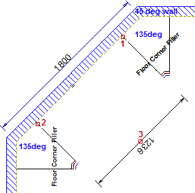
- Note the dimension measurement (1236mm) is reversed in comparison to the wall measurement (1800mm). (See Direction of Measurement discussed below).
To end, simply click 'Dimension' command icon or another command.
When you drag to place, you are able to set the dimension lines in various locations, just by holding down the mouse key and dragging until in required position.
Direction of measurement
The direction of measurement depends on the direction of the line you click along.
Example 1 - in the image shown above, the direction was right (1) to left (2). The measurement (3) is displayed in a reverse direction to the wall dimension.
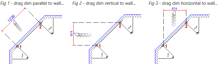
Example 2 - in the images below, the sequence of start and end clicks has been changed in each i.e. the direction was left (1) to right (2).
- In Fig 1 the measurement now displays in a reverse direction to the initial image i.e. it now displays in the same direction as the wall dimension.
- Note also, that you can drag the dimension line in different directions to suit your requirements. Stems have been turned on to illustrate.
Dimensions are associative
This means dimensions attached to objects in the drawing will resize automatically when the object is changed or moved to a different location. Turning on Snap To Handle will ensure that the dimensioning command tool will know which cabinet handle they are meant to be associated with.
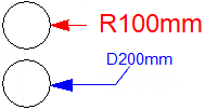
The Radial Dimension tool allows you to allows you to dimension placed circles, cutouts, benchtops etc- see Dimensions Radial Tutorial.
- First draw a circle
- Click the 'Radial Dimension' command.
- Click on (1) where you want to begin and then (2) where you want to end dimension.
The resulting radial dimension will be shown, to which a leader line can be added by clicking again away from circle. To end, simply click this or another command.
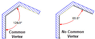
The Angular Dimension tool allows you to dimension...
- between walls with a common vertex - the nearest pair of adjacent walls are auto selected when you are outside snap distance.
- and walls without a common vertex - if you move the mouse closer, you can click on one wall and then the other i.e. you select walls that are not adjacent using two clicks.
Then after the first one or two clicks (depending on where you click) there is a movement of the arc dimension line until you click to place.
Double click to open DimSet Tool. Dimension Sets offer more powerful features which allow you to dimension drawings quickly and effectively to create the lines you need and set their height ranges and such before you place them on the drawing.
Dimension Sets (or DimSets) are collections of dimension lines where each line can be measuring a different part of a drawing. This is achieved by setting a Height Range for each line, which means that particular line will only measure cabinets which fall inside its upper and lower boundaries.
Select from dropdown menu arrow  Tool or Whole Page option.
Auto Dimension Tool
Tool option automatically places dimensions along a specified cabinet or wall.
After selecting the Auto Dimension Tool command, click on the cabinet or wall that you wish to dimension. If a wall is selected, only the straight section of it that was clicked will be dimensioned, not the entire wall. To Auto Dimension a corner cabinet, you can click on the half of the cabinet (Main or Extn) that you wish to be dimensioned.
Example Auto Dimension Tool
After clicking on the Auto Dimension Tool, we have clicked once on the Extn of the corner cabinet.
As you can see the red dimension line (Base_Cabinets) shows a dimension of 734mm and the brown dimension line (Overall_Wall) shows a dimension of 750mm. The reason is that the 'Gap Between Cabinet and Wall' is 16mm (click on image to view Options page).
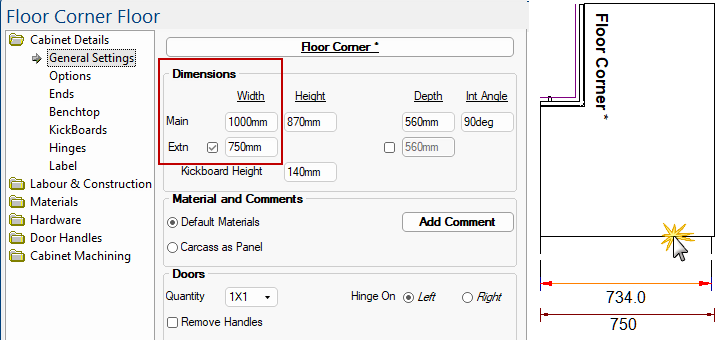
Click to view Gap details
The Auto Dimension function remains selected until you use another tool.
You can tidy up your plan, especially if some dimensions seem crowded, by manually moving dimension text. To do this, hold down the 'Ctrl' key and select individual text dimensions. Then drag text to required position. Dimensions can also be edited to change size and colour.
The Whole Page option automatically places dimensions to an entire drawing and is a handy feature, which tries to place DimSets on along each wall in the drawing in the best way it can find.
If final product is not exactly how you prefer it, you can always rearrange it to your liking by...
- changing the properties of the DimSet Tool after auto-dimensioning the whole page.
- Simply update the automatic DimSets by clicking the command again.
- OR manually move using left 'Ctrl' key, then click on the dimension number you want to move and drag it to new position.
If you wish to use this feature, then it is advisable to activate very early in your drawing, as it can take a long time to activate on complicated drawings.
This will only affect the DimSets originally created by the auto-dim tool i.e. if you added some extra DimSets manually they will not be affected.
Allows you to draw a line between two points while displaying the horizontal offset, vertical offset and total distance between them. This command can also be accessed on the Insert tab.
Be aware that this tool will measure either World or Page lengths depending on the Draw Coordinates selected in the ribbon.
After selecting the Tape Measure command, click on the drawing at the first point and drag the mouse towards the second point. You will notice that as you drag, a line is drawn between the two points with the current measurements noted on it. The end points of the line are affected by snapping if you have Snap To Grid or Snap To Handle enabled. When you release the mouse button at the second point, the distance and angle between the two points are copied into the Set Length and Set Angle boxes for convenience.
Snap to Handle can also be used in conjunction with the Handles drop list to make selection of specific items simpler and accurate.
Example
We want to measure between the two panels but as shown on the left, it is incorrectly measuring from a panel and a Wall Return.
With Snap to Handle enabled and selecting "<all sections>" from the Handles drop list provides the correct measurement.
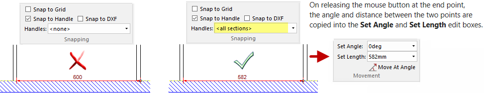
Important: Be sure to set Handles back to "<none>" when finished.
Each shape can be customised by right clicking on the tool, which will present the 'Format...Tool' option, as per example below. This will open a Drawing Tools Property Sheet which is referred to in each of the following discussions.
See also the following related discussions on:-
This command lets you insert rectangles onto a drawing in the same way as a Text Box. Using the Format Tool, you can chamfer or round the corners of the rectangle if desired. And you can select the edge line type and the fill type. For lines and fills which are not solid, there is also a background color to select. The buttons for background color are greyed out when solid line/fill types are used.
Right click Format... opens a Rectangle Property Sheet which has standard Size, Style, and Position pages.
NB: Position is only applicable if placed on drawing.
To correctly select a rectangle on the drawing page i.e. after it has been placed, it is important to note that a rectangle is solid, even though you can set its Fill to transparent. To select a rectangle after it has been placed, you only need to click anywhere within the rectangle. You do not necessarily have to select only the outline, useful especially if you plan to have a rectangle as a border for your drawing page. Make sure you use Send To Back on it so you can still select other objects. Alternatively, you may want to use a Poly Line as a border, which has no fill.
These commands lets you insert a circle or ellipse onto a drawing in the same way as a rectangle.
The circle command ensures that all points on the circle are equally far from the centre of the circle.
The ellipse command allows you to create an ellipse which is shaped so that when you add together the distances from two points inside the ellipse (called the foci) they always add up to the same number. Ellipses vary in shape from very broad and flat to almost circular, depending on how far away the foci are from each other. If the two foci are on the same spot, the ellipse is a circle.
This command lets you insert an arc (partial circle and also call the polyarc) into a drawing using 3 points of reference in an anti-clockwise direction.
To place an arc (or section of a circle) on the drawing...
- First click the position of the start point of the arc.
- The next click places the centre, mid-point, of the circle which the arc lies on.
- The third and last click determines the angle of the arc, and hence the position of the end point.
The best way to place an arc is to hold on the third mouse click so that the arc appears, but is not yet properly placed. You can then drag the mouse around, and the arc will follow. Either way, you can always drag the handles of the arc around after it has been placed.
Right click Format... opens a PolyArcs Property Sheet has standard Position and Size pages, and a Line page similar to that of the PolyLine.
The only difference is that Arcs do not have any options for arrowheads.
The PolyCurve tool can be used for placing a smooth curved line onto a drawing as it lets you insert a freehand spline curve into a drawing. Each click on the screen adds a node to the curve, which will be drawn smoothly between every three points that you place. It is different to an arc because it is a constant curve between several points (a spline), whereas the arc has a fixed radius.
The best way to place one is click the first point, then click and drag each following point to get an idea of how the curve works. A PolyCurve has two fixed endpoints with two control points in between which control the look of the curve. These control points do not necessarily intersect the actual curve. As with most things, the best way to figure it out is to experiment. Because you only get two control points, any clicks after the end point will not continue the smooth curve, but will start a new PolyCurve from the end point. You can drag around the various handles of the curve after it has been placed.
Right click Format... opens a Poly Curve Property Sheet.
It is the same as the PolyLine, with a Position, Size and Line page which has options for arrowheads.
Use the Polygon tool where you require a closed, straight-sided figure that you cannot draw using the Rectangle tool as it lets you insert a freehand closed polygon into a drawing. Each click on the screen adds a vertex to the polygon. For example,click at three places to get a triangle.
To do this:
- Select the Polygon Tool and click the mouse at the start position. This selects the first corner of the Polygon.
- Click to place following points of the Polygon. Do not be too concerned if it is not positioned quite right to start with - all the corners can be dragged around later. You may find it useful to have 'Snap to Grid' on.
- When finished, just select another tool.
Right click Format... opens a Polygon Property Sheet has standard Size and Position pages, and another one called Line & Fill.
This is nearly exactly the same as the Style page for rectangles, except it has no options for chamfering, rounded corners, and so on.
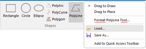
This command lets you insert a freehand line into a drawing in the same manner as the Polygon tool, except that it does not have to form a closed shape. Therefore it has no fill type and is just a series of joined straight lines. Each click on the screen adds a vertex to the line.
This tool is useful for creating borders on a template.
In addition to the standard Size and Position pages, the Poly Line Property Sheet also has a Line page.
This is similar to the Line & Fill page of the Polygon tool, but obviously without the Fill controls. Instead it has options for arrowheads on the ends of the PolyLine. You can turn the arrow on each end on or off, and also set the sizes of the arrow itself.
To 'Trim or 'Extend' you need to start with at least two polylines that intersect, as the trim tool helps to join precisely to other lines in your drawing. You can trim a line segment belonging to a polyline, polygon, horizontal panel or wall.
See Annotations Tutorial for full discussion.
Symbol items can be drawn up by each customer using single/multiple drawing tools, shapes etc. Symbols can also be an imported dxf.
These can then be saved as a single entity for future use, which allows the placed symbols to be resized and repositioned.
After selection of multiple shapes/items, click on this command button and it will be created but not saved.
Another way to do this is to use the right click menu option Use as Graphics Symbol.
See Tutorial
Snap To Graphics which controls whether you can snap to a graphics item.
You must use the
Save command if you want to use your created symbol in future drawings. If you do not save, then the symbols will only be available while you are using the current session of your drawing.
Draw Coordinates
Movements/offsets can be changed from World Measurements to Page Measurements.
- The Page view shows the measurement on the A4 plan.
- Page coordinates are for annotations text boxes, logos, decorative lines and so on.
- The World view is actual one to one size relative to cabinets, walls etc and part machining.
See Also
Tutorials
Library Basics and Properties