CabMasterPro User Guide
Annotations allows you to make a note by way of explanation or comment to your drawing. CabMasterPro provides a number of ways to do this.
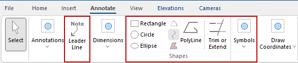
This tutorial discusses the commands highlighted above. These are...
See also: Tutorials/discussions for the following annotations can be accessed using the links:-

A Leader Line is a line that connects a data label and its associated data point. It is helpful when you have placed a data label away from a data point.
This is basically a Text Box with a Line that connects a comment text to a related point. Both the text and the Line can also be formatted before placement using before placement or after placement using the right click item menu. The You can enter/format text, in the same way as a
 command button.

Click to view Leader Lines properties and Line page amendments
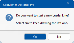
command button and select 'Yes' to message.
Click No if you want to keep drawing the current leader line (or shape as applicable).
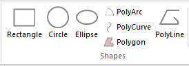
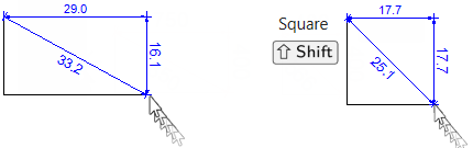
Simply click on the Rectangle command button and then click on drawing and drag.
Simply click on either the Circle or the Ellipse command button.
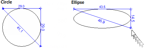
Click to view Ellipse resized with proportion maintained
Click on the PolyArc command button to create an arc or a series of arcs i.e. to create a shape (click on image).
The same process can be used to create a Polygon which is a closed shape.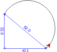
Click to view steps and example
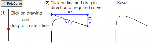
Click on the PolyCurve command button to make the curved lines, then...
To Trim or Extend you need to start with at least two polylines that intersect, as the trim tool helps to join precisely to other lines in your drawing. You can trim a line segment belonging to a polyline, polygon, horizontal panel that has curved edges or wall.
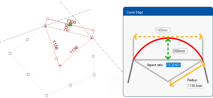
In this example, we will create a pentagon shaped HPanel and curve one edge.
HPanel example - click to view
Click and setup an HPanel, then curve an edge (using rclick menu).
In this example, we clicked 5 times to the vertices needed to make a pentagon shaped HPanel, then rclicked on the top edge and curved it by typing in the 200mm as shown…
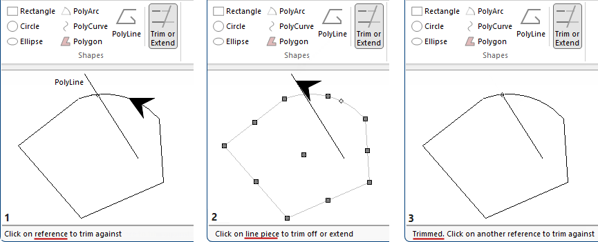
Then a two point Polyline was added to the HPanel created above.
Next click on Trim or Extend command and watch the prompts on the status line at the bottom of the screen.
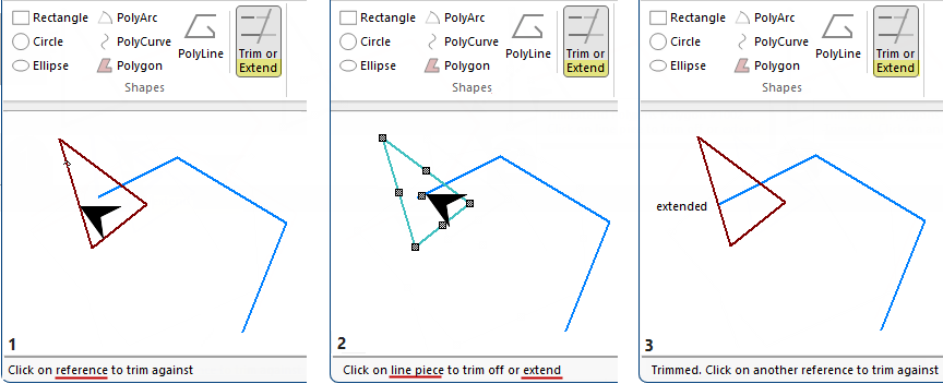
Click to view another example i.e. a triangle shape trimmed at different points
To Extend you essentially repeat the same steps as above, except we click near/towards the reference object you want to 'Extend' to.
Symbols can be drawn/created using drawing tools (in the Annotations group), Shapes or by importing a dxf.
These can then be saved for use in future drawings or used in an individual session (i.e. only be available for selection until you close the application).
To create a symbol, simply draw using single/multiple shapes, pictures, leader lines etc or import (discussed below).
Then select your newly created symbol and either...
click on the Annotate > Create from Selection command;
or
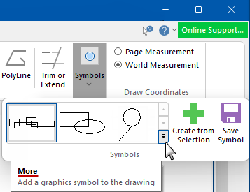
It will be added to the ribbon palette in the Session symbols area as a single entity. (Click on More  to display as per example below).
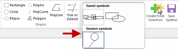
Click to view creation of Session symbol and menu option
When placed on your drawing, symbols can be resized and repositioned as required.
If you want to Save for future use, click Save Symbol, as shown.
This will be saved as a .qtd file, in the ToolData folder (click on image) and displayed in the Saved symbols area.
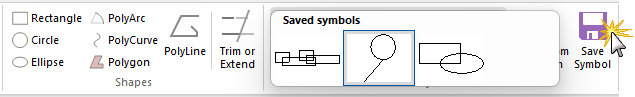
Click to view effect of clicking the Save Symbol
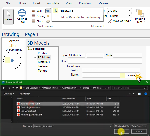
Symbols can also be imported using the 3D Model tool.
In the following example (and video), we located some dxf files and placed them in a folder called "DXF Files".
- Click on the 3D Model tool and place on drawing;
- Then double click on placement (or use the Format menu option) to open the 3D Models property sheet (as shown);
- Click on the Browse button and select the required file;
- Click on Save Symbol command to create a qtd file in the ToolData folder (as discussed above).
Watch our tutorial video to find out how you can enhance your CabMaster drawings by creating/importing, saving and using Graphic Symbols. [4:54 mins]