Wall Opening and Arches Tutorial
Openings, such as a window or a door, can be placed in a wall. Other ways to create an opening in any shape, can also be done by using...
You can add a custom shape that cuts the hole through the wall wherever it is placed and can include curves and items such as for a servery.
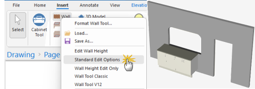
In this tutorial we will using the Standard Edit Options Wall Tool, shown right, to create a curved hole in the wall to be used as a servery.
Curved walls can also be created and are also supported using EDF Imports. See the Import eTemplate / EDF file Tutorial which includes a data file (qid) for download.
Developers can create cutouts by creating a new cabinet item that represents the opening.
Step 1
Place a wall e.g. 4800mm in length and 2700mm to top. Here we have added some cabinets to use as a visual aid.
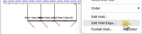
Then Edit Wall Edge... required using either the right click menu option (shown) or the Breadcrumbs Bar.
Click to Expand
Step 2
Now we will use the Machining Editor and the Rectangle tool to cutout a door and servery.
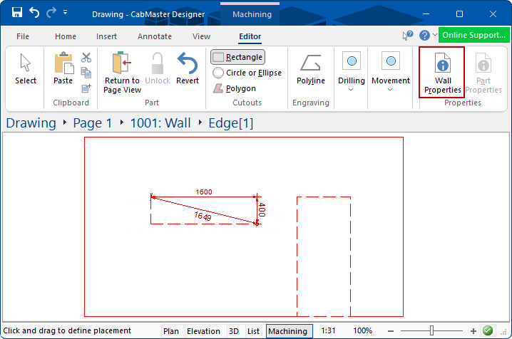
Click to view Wall Properties
The Walls Tool has an option to View Custom Shape which can be turned on/off. Click on above image to view.
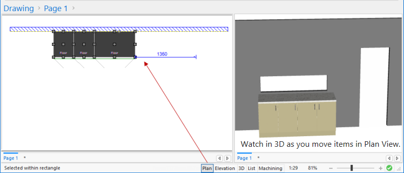
The Split command can be used to have multiple views. As shown here, we have moved the cabinet under the hole we created and moved the cutout down to just above the cabinet. As items are moved or changed, the 3D image will automatically update.
Step 3
Format the cutout using one of the right click menu to move, chamfer, fillet or remove corners, as required.
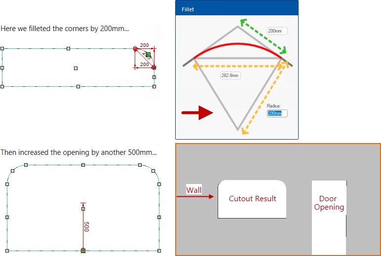
In this example, we will fillet the top corners and drag the mid handle to resize.
There are multiple ways to accomplish the same thing, it is just a matter of personal choice.

Remember to Unlock - see the topic on Part Editing for a more detailed discussion.
The Format Machining... menu option is another way to resize and reposition cutouts.
Result
An alternate way to create a hole in a wall is by using the Wall Tool command and property sheet.
To place the corners and end-points precisely, you need
Snap to Handle and
Snap To Grid turned ON - see
Grids and Snap Tutorial.
Step 1
Select the Wall command  on the Insert tab and draw a solid wall segment to the beginning of the hole in the wall.
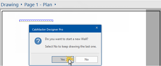
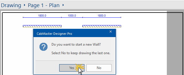
- Click on the Wall command again.
- Click Yes to the message asking you if you want to "...start a new Wall?"
Example: First Wall
Step 2
Select the Wall command again and finish the wall on the other side of the gap, as shown in the example.
Example: Second Wall
Click the Wall command again and Yes to the message asking you if you want to "...start a new Wall?"
Step 3
Draw another section of wall across the gap and double click on this section of the wall to Format....
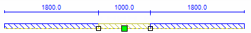
Example: Third (middle) Wall
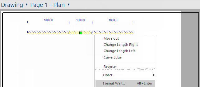
Click the Wall command again and No to the message asking you if you want to "...start a new Wall?"
Double click on the middle section of the wall or select Format Wall... from the right click menu, as shown.
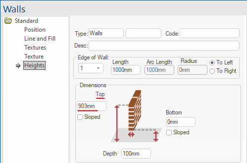
Step 4
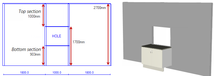
You need to set the Top height of the bottom section of the servery.
This is done on the Heights page of the Walls property sheet and should be based on the Top of Bench height on the Job Defaults page of your - click on image.
Click to view Walls in 3D Display and corresponding Job Defaults
Step 5
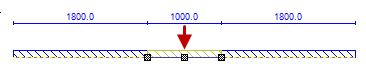
To form the top section of the servery wall, place another section of the middle wall (1000mm) over the one you created in step 3 above.
In Plan view, because you have a wall placed on top of a wall, it will not look any different.
A good idea would be to place a Manual Elevation on the Plan to see the effects as steps 5 and 6 are applied.
Elevations are associative which means that if you make changes after defining the elevation, will automatically update the elevation - click image.
Click to view Manual Elevation before the top part is added
Step 6
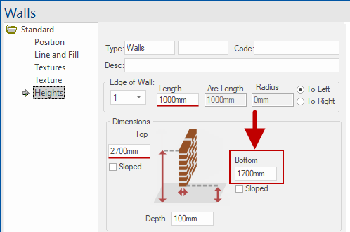
Double click on overlapping placed wall and change the value in Bottom to the lowest edge of the top section.
Example: Change Bottom Dimension
Top Dimension should be the default height of ceiling in the properties, in this example 2700mm - see note in Walls Tool.
In this example, we have changed the Bottom Dimension to 1700mm. Click image to view elevation on plan.
Click to view Elevation on Plan after top part added
Step 7
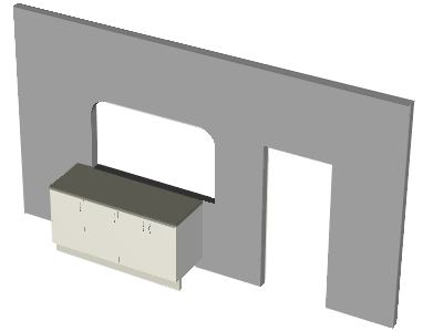
You should now have a complete wall except with a hole in it as shown here in Wireframe and Solid 3D view with a cabinet added.