CabMasterPro User Guide
The Machining Editor provides commands for editing a selected cabinet part and applied cutouts.
In this topic we will discuss...
Remember that you first need to click on the Unlock command button before you can edit.
See Tip on Machining Editor and Depth.
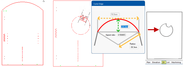
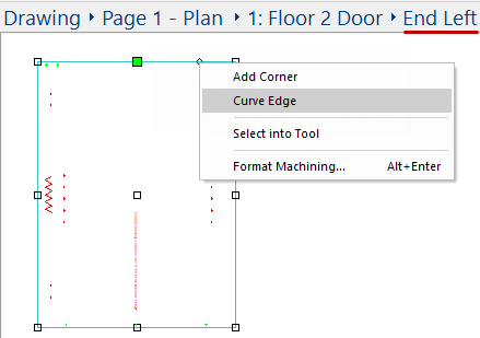
To curve edges use the right click menu option, as shown.
Click on the required part/cutout, the border will turn blue and you will see handles;
Select the centre handle (highlighted in green) and use the right click menu to select 'Curve Edge'.
Click to Expand
Then simply...
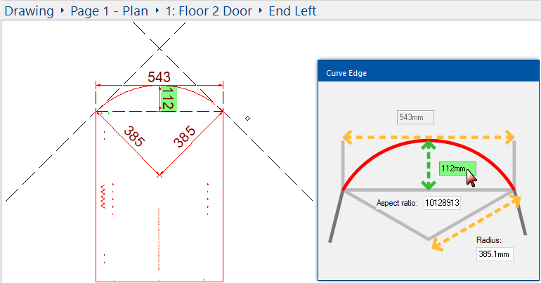
Curved Edges can be added to parts or cutouts
Here we see the part now displayed with curved edges. These commands also work with cutouts, as shown.
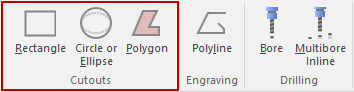
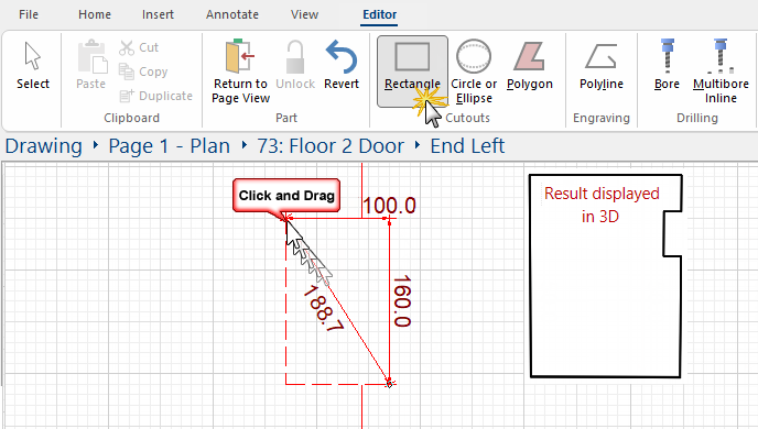
Create a notch by using the Rectangle or Circle cutout.
In this example, we are creating a notch on the right side of the 'End Left' part of a cabinet using a Rectangle cutout.
The View > Grid has been turned on and we have zoomed in on the required area.
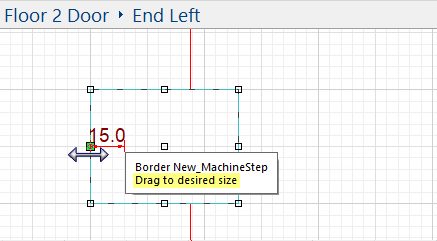
You can Move In / Out by dragging a selected point. The example shows the mid point moved out (left) by 15mm.
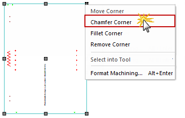
To move, chamfer, fillet or remove corners use the right click menu, shown below. To chamfer the corner...
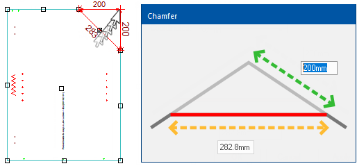
This method can also be applied to a cutout
In this example, we have added a Rectangle cutout and then Chamfered the corner. The resulting cutout can be seen in 3D.
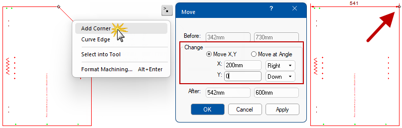
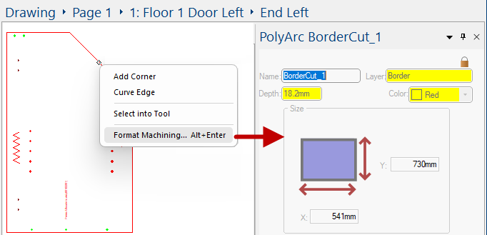
To add a corner use the right click menu option which will open a Precise Movement Input dialog.
This means that we will need to know some details about the part/cutout first.
Step 1
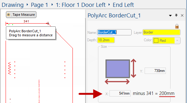
Right click on part and select Format Machining and refer to the Size details - which here shows the X dimension of the part is 541mm.
You can also use the Tape Measure as per Step 2, if preferred.
Click to view Machine Editor window
Step 2
Now we will measure the relevant border - here we have used the Annotate > Tape Measure command.
From this we can determine that we need to move the corner by 200mm (i.e. 541mm - 341mm).
Step 3
Right click on the relevant border and select Add Corner.
To input a specific dimension, just press keyboard dot
once (and let go) and a precise movement input box appears and you can input a variety of different options. Here we are going to Move X 200mm to the Right (Ensure Y:0mm)