CabMasterPro User Guide
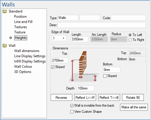
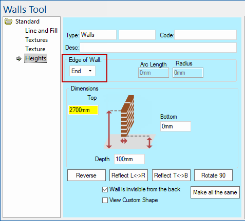
This topic discusses the Standard > Heights page of the Standard Wall Tool, available when placed on a drawing (which has a Position page).
 |
For quick links to more information, click on  the options or another page.
This drawing tool is located on the Insert tab and can be customised. See also webinar and/or tutorials on Walls, Floors and Ceilings.
Custom Wall Tools (e.g. v12) have been created to simplify category options and are discussed where applicable.
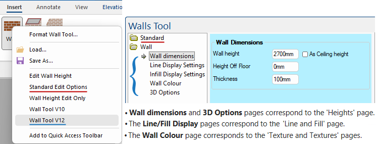
The Wall Height edit box allows you to manually set the height of the wall.
The Height Off Floor setting defines how far above ground the wall starts.
The Thickness determines how thick (depth) the wall itself is.
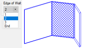
The Edge of Wall (or Wall Number) drop list allows you to select and control each section (edge) of the wall.
In Ortho preview mode you can see the selected section highlighted i.e. in this example Edge 2.
The End is the end of the last section, in this example section 3. The height of each vertex can be controlled - see Dimensions. If the wall has 3 sections (edges), then there are four vertices - that is why the Standard Edit Options combo for 'Edge of Wall' has one extra 'edge' called End to allow you to set the height at the end of the last wall edge.
The End edge of wall has no actual walls.
Click to view the Job Defaults page of the Drawing Properties
Developer Software Users: There is a middleware built-in variable called EdgeIndex which, when setting up wall heights and textures, is used to select an edge of the wall and calculate other properties of that wall edge. See Walls Tool Formula Reference.
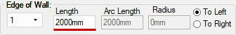
The length of each selected section of the wall can be manually updated. As you change the 'Edge of Wall' combo, it updates the wall on the drawing.
In this example, section 1 of the wall is 2000mm in length.
Click to view in both Plan View and Ortho mode preview
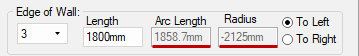
If the edge is curved, it also shows you the Arc Length, which is longer than the edge length due to that curve, and the Radius - click on image to view example.
Click to view curved wall
Walls in CabMasterPro supports "True" radius curves. This means that when an image or texture is applied to a curved wall, this image will accurately stretch along the wall surface, along the straight and around a curve, together (as shown).

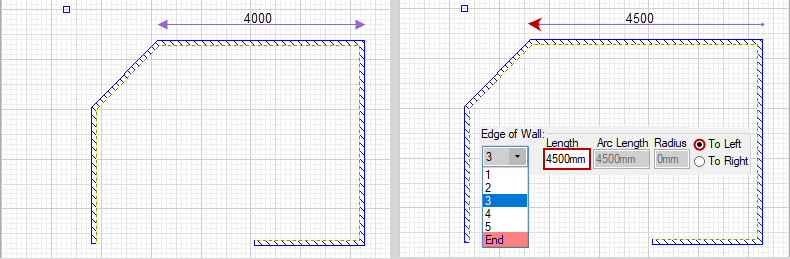
The setting of the radio button 'To Left' or 'To Right' determines whether to move the vertex at the left end or the right end of this wall edge, when you change its length.
If you change the length, say increasing it from 4000mm to 4500mm, then the edge is lengthened by some amount. In this example, it extends 500mm to the left or to the right (looking at the wall from the front).
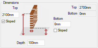
The dimensions section controls the height and depth of the wall.
The Bottom (or Off Floor) setting defines how far above ground the wall starts, the Top (or Left/Right Height) setting defines how far above ground the wall finishes and the Depth determines how thick the wall itself is.
The Sloped check box allows you to slope each section of a wall. When working with sloped walls, you have to specify the start position per wall i.e. the Next Top height is set by selecting the next wall edge (therefore height is greyed out/unavailable for editing) - see Wall Sloped Tutorial.
Click to view Sloped wall

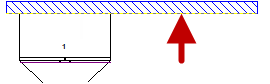
The yellow perforated line on the wall denotes the placement side for cabinets.
Click to view right click menu command
If your wall is not the correct way, when you try to place your cabinets, they may appear upside down.
To correct this problem, select the wall and use Reverse command on the Tool or the right click menu or use the Keyboard Shortcut: S
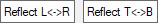
The Reflect L<->R causes it to be reflected in the X dimension (Left to Right, hence L and R).
The Reflect T<->B causes it to be reflected in the Y dimension (Top to Bottom, hence T and B).
Reflective properties work best on surfaces that are reflective or glossy in real life, like glass panes, metal sinks, and even polished benchtops. They are more noticeable when the viewpoint is moved around the surface, so the brightness changes dramatically. Curved surfaces show up even better, as can be seen above.
The reflection coefficient is a number between 0 and 100. If it is greater than 0, the surface is reflective. 100 is like a mirror.
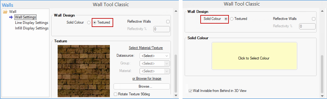
Solid Colour is the colour that the face is drawn in for Solid renderings, used as the stain colour when the Solid Color radio button is enabled.
- Click the colour preview box to open a Color Select dialog where you can select a colour to use on the wall face.
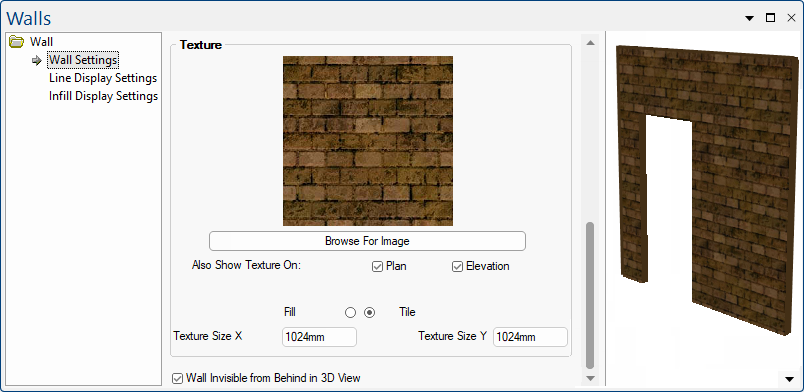
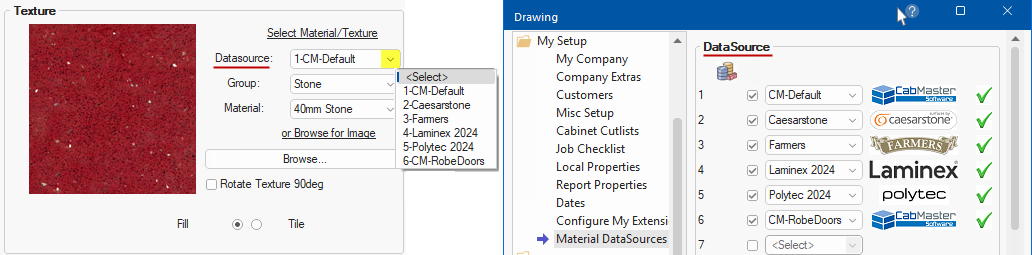
Texture options are provided when the Textured radio button is enabled and allows you to control the tiling effect.
- Either Browse for an Image or Select a Material/Texture.
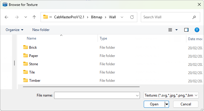
Browse for Image allows you to quickly locate a texture in your Bitmap folder.
Each texture is stored as a bitmap, although they may be saved in a variety of different Image Formats. They are usually created by scanning in samples or photos of real material. CabMasterPro provides a large selection of textures when you install it, and new colour ranges or styles can easily be added with future updates.
Select Material/Texture can be customised to the users preference.
CabMaster Software™ uses a default set of materials [CM-Default] that can be customised to the user’s preference.
You might want to use or create your own material supplier data sources that. These can be enabled on the My Setup > Material DataSources page in the Catalog/Drawing Properties.
See topics in the Library User Guideon What is a Material DataSource? and How to Create a New DataSource.
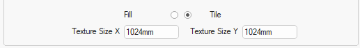
Tile Texture Size X/Y edit boxes are only provided if the Tile radio button is enabled. Like a tiled texture, you specify how large a texture is meant to be in real life. You enter the dimensions of the texture, such as 300mm, and it will be kept at that size and tiled across the face as necessary. The dimensions of the texture will not change if the surface changes size - only the number of times it is tiled.

Clicking the Rotate 90 degrees button causes the wall to rotate 90 degrees clockwise which could be useful when you are using a wood texture and the grain is running in the wrong direction.
This same effect can be made using + or - keyboard shortcuts.
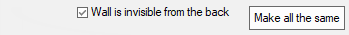
Using the Standard Edit Options, this checkbox only applies to the edges (not End) and determines whether the back of the wall (i.e. when rotated) is visible or not in 3D Display. Each section (edge) of the wall can be set individually.
In the example (click on image) Edge 1 is visible but Edges 2 and 3 are invisible.
If you want to all edges to be the same, then check/uncheck on any edge and click Make all the same button.
Standard Wall Tool - Click to view in 3D
The Standard Edit Options, shown above, has a View Custom Shape check box that allows you to view a cutout in a wall.
Some custom Wall tools do not require you to use this setting but still provides the ability of creating a cut out when items such as windows and doors are added.
See tutorial on Doors and Windows.