CabMasterPro User Guide
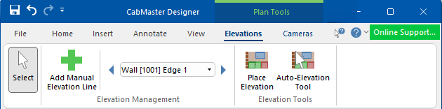 |
To locate information about any commands or tabs,  click on the area of interest on ribbon image above.
These elevation tools are only available when in Plan View and are different to those generated from the View tab > Elevation View of cabinets along each wall. If there is no wall then no elevation gets generated and you cannot edit the elevation.
For a discussion on how to format and edit elevations that are on your plan, see the Elevations Tutorial.
Plan Tool Elevations allows you to have as many elevations as you want, added to the same Plan page or viewed on separate pages.
To move an elevation to a separate page, first ensure that the drawing Page you want it moved to is already created. Then select the elevation to be moved and either...
DO NOT use copy/cut and paste as this may create duplicate walls.
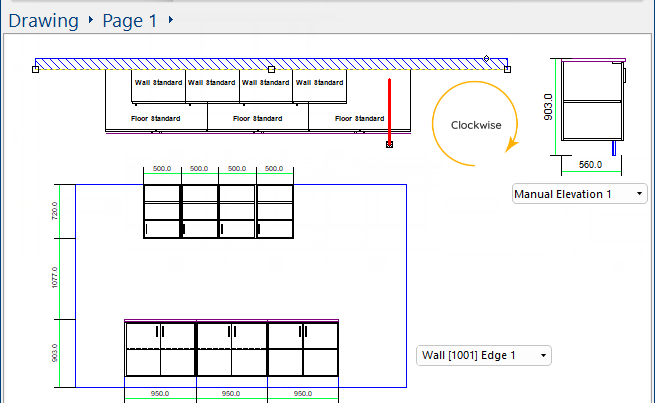
Example of placed elevations
Shown here are two sets on the same page.
- Wall [1001] Edge 1 - is an elevation along the top wall and provides details of all cabinets on it.
- Manual Elevation 1 - is a cross-section elevation, made by placing the elevation points across a cabinet (in a clockwise direction).
Click on the image to view an example of 'Move to page'.
Click to view 'Move to page' option
Dimensions are added to the elevations automatically. Elevations are associative, which means that if you insert or delete cabinets after defining the elevation, then CabMasterPro will automatically update the elevation. What and how elevations are displayed can be controlled on the Elevation Property Sheet.
It allows you to select one or multiple items e.g. walls, elevations or cabinets, at the same time.
See topic on the Select command for more details.
Manual elevation lines can be created in addition to the automatically created elevations along each wall.
A manual elevation can be added to a wall and are also very good for islands but be careful how far 'Infront' and 'Behind' elevation lines are set because you might want to show both sides but not show what is behind the other cabinets.
To create a manual elevation, click the 'Add Manual Elevation Line' ![]() command button and then drag a line between two (2) points in Plan View, in a clockwise direction.
command button and then drag a line between two (2) points in Plan View, in a clockwise direction.
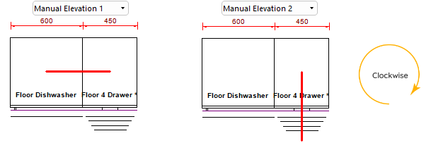
Shown here are two examples of a manual elevation.
- A solid red line will be displayed defining the elevation for placement.
- Each will have a reference created and added automatically to the Management drop list for future selection.
Walls are not required for creating a manual elevation.
Always add the elevation line in a clockwise direction, parallel to the cabinet/s, otherwise the elevation will be displayed incorrectly as mirrored or distorted. Holding down the Shift key while creating a manual line will ensure a straight line, as it locks it to the closest 45 degree angle.
If you do not like the resulting placement, select "Undo" ![]() from the Quick Access toolbar.
from the Quick Access toolbar.

This command lets you insert an elevation of a row of cabinets or a specific area on an individual cabinet to a drawing in Plan View.
Select the Elevation (as per drop list) and then simply click on the Place Elevation command button and click on plan to place.
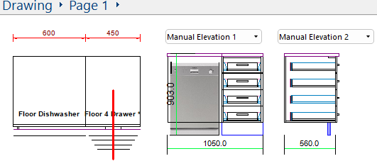
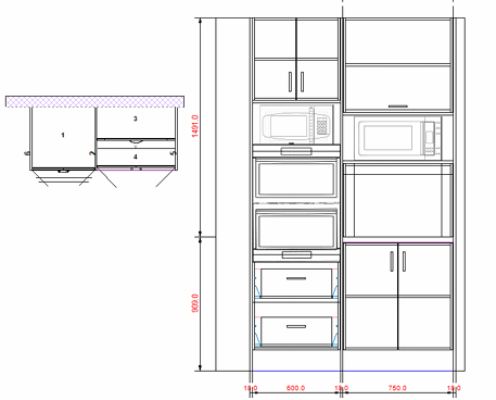
Shown here are the placement of the two Manual Elevations created above.
- Manual Elevation 1 - shows elevation details of the Floor Dishwasher and the Floor 4 Drawer.
- Note that dimensions are aggregated i.e. the total length is displayed.
- Manual Elevation 2 - shows side view elevation details of the Floor 4 Drawer.
Click to view Formatting options
Placed elevations can be formatted to resize, show cabinets in wireframe/hidden/solid view, show/hide dimensions or turn on/off aggregated dims. Either double click on the placed elevation or use the right click menu Format option. See discussion for Elevation Tool.
To delete an elevation line, either select the corresponding elevation and hit the keyboard delete button or use the right click menu option. (This will only work if you have one elevation of an elevation line. If you have multiple elevations of the same elevation line, then you would need to delete all corresponding elevations).
The Appliance Cabinets (Wall Appliance, Ovens, Microwaves etc) have had their models updated to include elevation images of the selected models for better renders and display.
This is automatically populated as you create walls or manual elevation lines. A red line in Plan View indicates the plane of the current Elevation View, as shown above. When you go into Elevation View, this is the line that will be elevated along. Selecting this function again will hide the line.
Use either the Navigation Arrows or the Elevation View drop list to select the wall or other elevation that you want.
Use to navigate to previous elevation view.
Use to navigate to next elevation view.

Automatically adds an elevation for a wall, a single cabinet or a run of cabinets.. Simply click on the tool and then on the specific item/s - see Tip.