CabMasterPro User Guide
 |
For quick links to more information, click on  the options or another page.
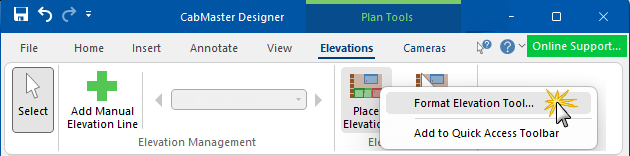
This drawing tool is located on the Plan Tools | Elevations tab and can be customised with the right click Format... option on the Place Elevation command.
Example
Elevations can be added to the same page or viewed on separate pages. Dimension lines are added to the elevations automatically and are associative, which means that if you insert or delete cabinets after defining the elevation, then the elevation will update automatically.
Refer Common Controls.
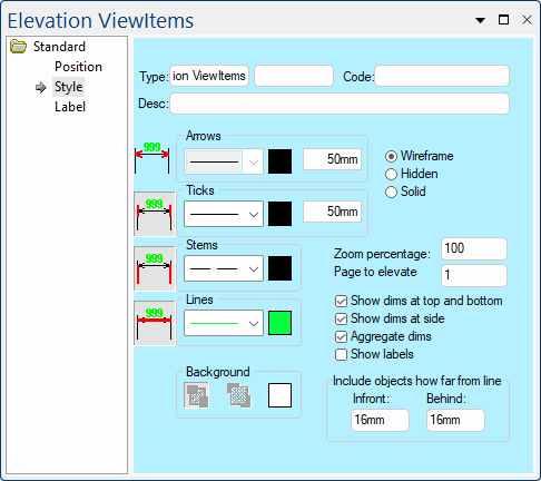
This set of controls is used to specify and display dimension lines.
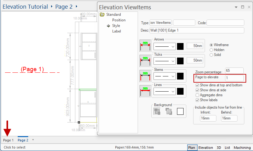
Zoom percentage sets what size your elevation is displayed. This zoom is relative to the scale you have set for the drawing itself, so if you set 100% zoom percentage here, the elevation will be at the same scale as the rest of the drawing. If you, however, set 50%, the elevation will be at half as large a scale on the drawing.
It also controls the size of the 'Page to elevate', which determines the drawing page that the elevation is generated from.
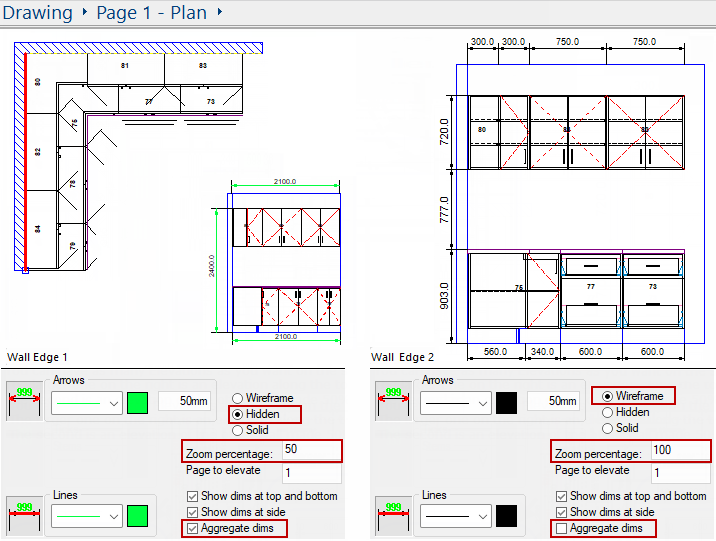
Example of placed elevations
In this example, the elevation for Wall Edge 1 is displayed at 50% and Wall Edge 2 is displayed at 100% with different styles applied.
It refers to the page that the elevation line is on, which in this case is Page 1 (click image below) as we have moved the elevation to Page 2.
Click to view Page which has the corresponding elevation line
The elevation render can be selected using one of the three (3) radio buttons...
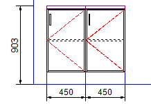
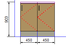
Wireframe
Wireframe shows the shape of each cabinet, along with indications of the thickness of the carcass and shelves.
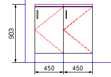
Hidden
Hidden shows the shape of each cabinet, but does not show anything behind the doors.
Solid
Solid shows the shape of each cabinet, with colours of the doors and kickboard, but does not show anything behind the doors. The colours are a plain (non-textured) single-colour representation that is based on the colour of the doors and kickboard that you have selected.
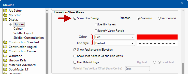
Elevations can be further enhanced by turning on/off the Show Door Swing option on the Display > Options page  of the Catalog/Drawing Properties [F4]. The colour and line style, and more, can also be changed here.
Display Options for Door Swing
The show flags determine different characteristics included in the elevation.
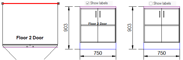
Show dims checkboxes allow you to control where dimensions are displayed. Select either or both options...
The Show labels checkbox allows you to show, or not show, the Label display as designated in the View Options [F9] > Visibilities page.
Refer to Aggregated Dimensions.
This is a compact version of the Transparency and Back Color controls from the common Line page and are only available when the selected Lines Style has gaps in it e.g. a dashed line.
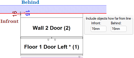
The InFront and Behind fields are the same as those on the Lines page of the DimSet tool and determines how close a cabinet has to be to a wall for it to be counted in dimensioning. The values are for the whole DimSet, not on an individual line basis.
If you have some cabinets which do not reach all the way back to a wall, you can increase the "InFront" value to the width of the gap so that they will be taken into account when that wall is dimensioned. These measurements select how far from the line chosen to have a elevation applied to it items are included.
Generally a very small distance can be applied here, as you will often only want objects which are connected to the line and not objects close by.
Be careful as some items have a clearance from the wall, so you will have to increase this value if you want them included - see Viewing the Elevation tutorial.