CabMasterPro User Guide
The View Options [F9] available are dependent on the View Type, as shown, and allows you to filter what is viewed and how they are viewed.
Available Options are dependent on the View Type
and are accessed using...
The Machining Options* page is only made available if the Show Machining option is enabled.
Machining can only be seen when in 3D Wireframe view.

Click to Expand and view an example of the use of Machining Options
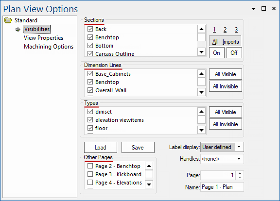
The options on the Visibilities page allow you to control what is visible on the drawing page.
The current section handles can be managed using a side column in the section visibility list, so that handles for multiple section types can be selected and displayed at once.
This is replicated on the View tab, displayed as a list separated by semi-colons - click here to view comparison
The existing View ribbon interface remains in place, and where multiple section types have been selected, they will be displayed as a list separated by semi-colons. The current selection is also saved between CabMaster sessions.
As you can see, the Plan View Options replicate the Handles selected from the Snap to Handle selection.
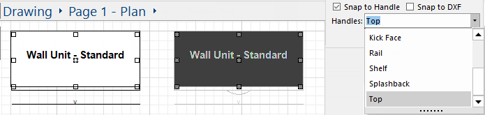
Click to compare with the View Properties page Handles selection click drop list
This allows you to control which cabinet sections will appear, and affects both 3D and plan views. It is very useful for speeding up the generation times of your 3D views. For example, if you are displaying the doors of your cupboards, you cannot see anything inside. Therefore, you may want to turn off the display of all internal sections, such as shelves.
By controlling section visibilities, you can also generate plans of certain parts of your design. For example, you may wish to print out a plan of just the benchtop layout. You could make all the Sections invisible and then turn on the benchtops. To do this, click the "Off" button next to the Sections list which automatically uncheck's all the section boxes, hiding them. You would then find the relevant benchtop sections in the list, and re-check their boxes, making them the only ones visible. Make sure you mark both the actual benchtop sections and their containers (In the example above, this would be "Bench Top" and "BenchTop_Laminated_top").
Similarly, you can also hide different dimension set types. As with section names and cabinet types, simply mark the boxes next to the dimension types you want displayed.
A useful example of this would be to create a benchtops plan (by hiding all sections expect for benchtops), then also hide all dimension types except for benchtop measurements. For more on using Dimension Sets, see the Annotate tab and Dimension Set Tool.
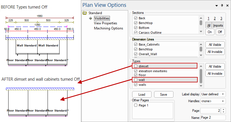
You can also control Visibilities by the Type of cabinet/item. This is used in exactly the same was as the section name list.
The example below shows wall cabinets turned off. Type also includes items such as dimset etc. Click the All Visible button to unhide.
Example
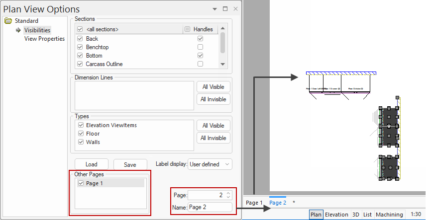
Allows you to include an exact copy of another page (from the same drawing) on the current page.
Like other visibility lists, simply enable by ticking the checkboxes for the pages you want displayed. This will produce a copy/exact duplicate of a page which can be edited just as if it was on the current page.
A common usage of this feature is to show different areas of the drawing on separate pages. See Using Multiple Pages discussed below.
You could have the full drawing on Page 1, then a benchtops Plan on Page 2, a kickboard Layout on Page 3, etc.
To do this, on each page mark Page 1 as visible, then make all but the relevant sections invisible.
In the following simple example, Page 1 has a horizontal wall with cabinets and Page 2 has a vertical wall with cabinets (which is the selected page). By ticking the Other Pages checkbox for Page 1 a copy of page 1 is presented on Page 2. This allows you to move/modify the wall/cabinets from Page 1 exactly the same as if it was on that page.
This allows you to change the label display on your cabinets by using the drop list.
The Handles drop list allows you to select from a list of sections in the current drawing. By selecting one, you will allow CabMasterPro to snap to that section as well as the nominal cabinet handles. See View > Handles.
You can save and load pre-defined CabMasterPro Visibility dialog settings, which can then be used in any drawing, and on any page. Visibility Sets as they are called are saved in files with extension .QVS, and store any changes you make to the dialog - which sections, cabinet types, and dimension sets you made visible or invisible. Note that it does not save which page copies are visible, this is part of the drawing itself.
To save the current visibility settings to a QVS, click the  button above the "Other Pages" list. To load one, click the
  button and select the QVM you want to open. This will replace the settings on the current page.
QVS's can be used as visibility "templates", for example, a kickboard layout. If you wanted one of these for every drawing, which shows only kickboard sections, walls and kickboard dimensions, you could just do it to one page, then save it as a QVS called something like "kicks.qvs". Then every time you needed a kicks layout, open the Visibilities dialog on a blank page, copy the main drawing page (see "Including Other Pages"), and load up "kicks.qvS".
The options on the View Visibilities page allow you to turn on/off features such as Grid, Snap and other controls.
Click to view page and comparison to View tab commands

Click to compare with the options on the View tab
Template Items, such as text boxes, graphics lines, logos etc that got added because they are part of a template, are not editable normally. This prevents users from accidentally editing, or dragging, resizing etc a template item.
However if you want to deliberately change a template item, you can temporarily check the Allow Edit of Template Items checkbox, but it is recommended you turn it off again when done.
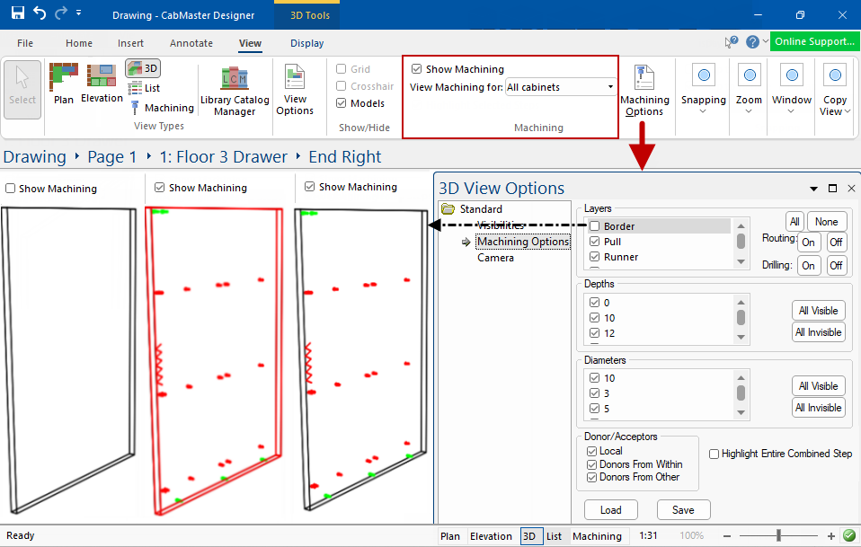
The Machining Options page allows you to filter out machine steps. See also View > Machining Options for examples of use.
Click to view options
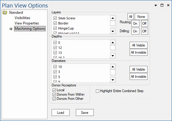
Filters: You can use filters to restrict viewing to just machining of interest i.e. you can ...
See also 'Filtering Machining' in 3D View and 3D Preview Pane.
Highlight Entire Combined Step:
Machining from different machinesteps will automatically combine into one path where this is possible. (The machining must be in the same layer and have the same depth).
When multiple machine steps combine, it is sometimes helpful to see the partial steps individually, but sometimes things are clearer if you see the entire combined step. You can control visibility using this checkbox.
An example might be a machined rectangle where the four lines are defined by separate machinesteps, but together they make a rectangle. When you click on the machining view to select one of the lines, this setting determines whether the whole rectangle is selected, or just the single line you have selected.
In the View > Machining group of commands the Show Machining checkbox can be used in conjunction with the Machining Options page.
As shown below right, you can use filters to restrict viewing to just machining of interest. Here we have turned off the 'Border' layer.