CabMasterPro User Guide
In this tutorial we will use the CM-Parts library to create a combined item to demonstrate the freeform features.
Features discussed in this topic are...
Place required cabinets/parts on drawing (for this tutorial create a new drawing)...
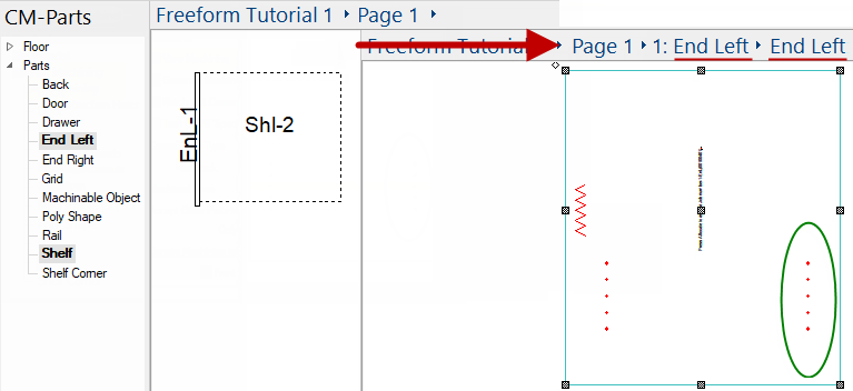
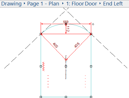
Here we used the Breadcrumbs Bar to view the 'End'. Notice the shelf has already donated holes to the 'End'.
To open the machine step properties, double click on the area of interest - in this example, one of the donated holes circled above.
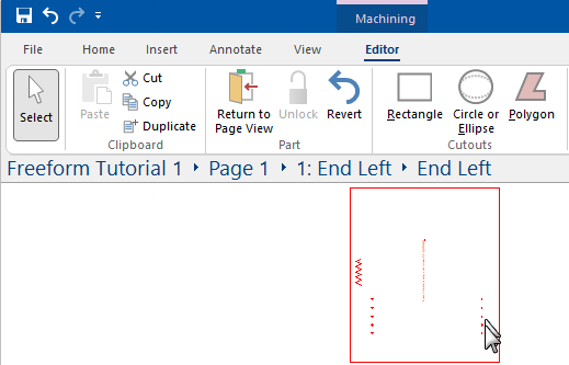
The Select command ![]() must be enabled and part Unlocked
must be enabled and part Unlocked ![]() (command icon will be greyed out as shown below).
(command icon will be greyed out as shown below).
To relock the part, use the Revert command button. See Part Editing.
As seen in the example below, the properties inspector provides related information, which are reflected on the status bar.
Click here to view the Property Inspector
Here you can see the properties of the Multibore InLine (holes) selected and the Start/End Points reflected on the status bar.
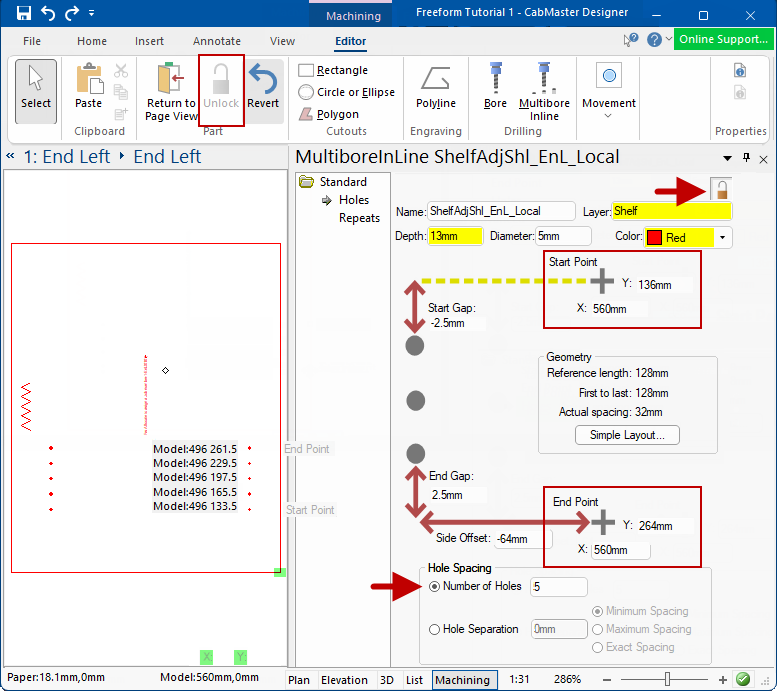
You can use the properties inspector to edit the part, for example, you can adjust the position and amount of Holes and spacing.
There are a number of ways to Move points.
Example
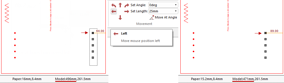
Notice that the selected points have moved 25mm to the left and the movement is confirmed on the Status Bar. (Measurements using Tape Measure have also been added).
The image on the left shows the Status Bar Model X position as 496mm. After the move, the Model X position is 471mm i.e. 496mm minus 25mm.
Example
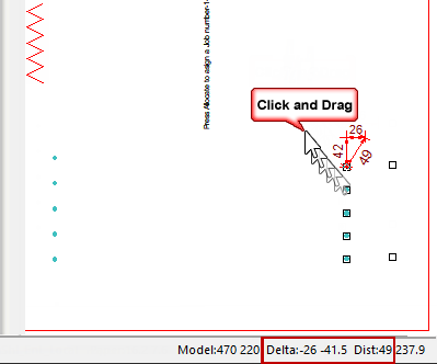
Notice the Status Bar here, the Delta reflects the drag movement measurements.
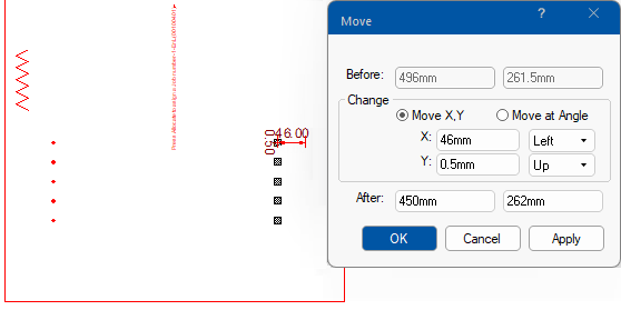
Activate by pressing the keyboard dot ![]() while starting to drag. The resulting dialog takes over and allows you to specify a precise movement.
while starting to drag. The resulting dialog takes over and allows you to specify a precise movement.
Example
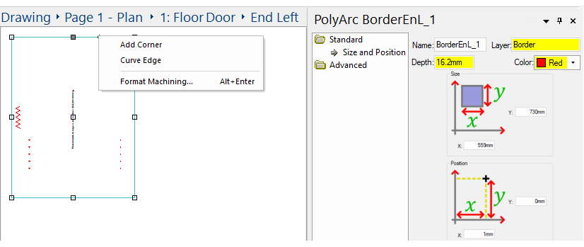
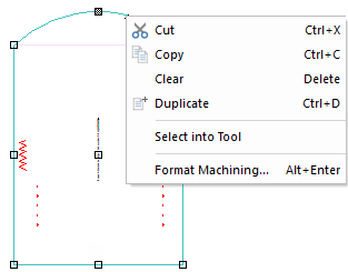
We can also edit the edges of the panel. For example...,
Example
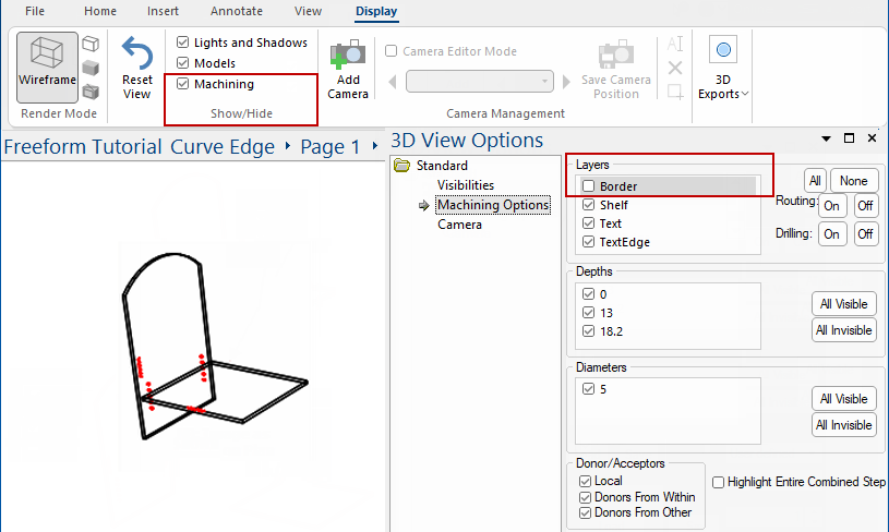
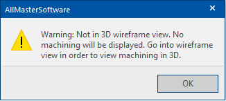
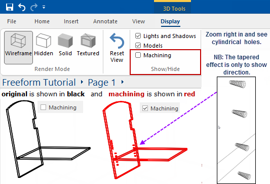
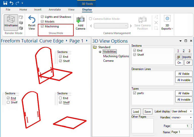
Machining can be viewed in 3D Wireframe by using the Show/Hide Machining option on the Display tab.
If you select a render mode other than Wireframe you may get this message!
See also topics on 3D Navigate and 3D Effects menu commands.
You can also zoom in and out and pan in the 3D view - see Mouse Shortcuts.
If we zoom in, we can see that the holes are tapered so we can see which direction the holes are drilled.
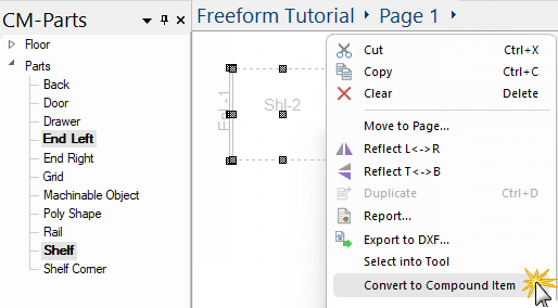
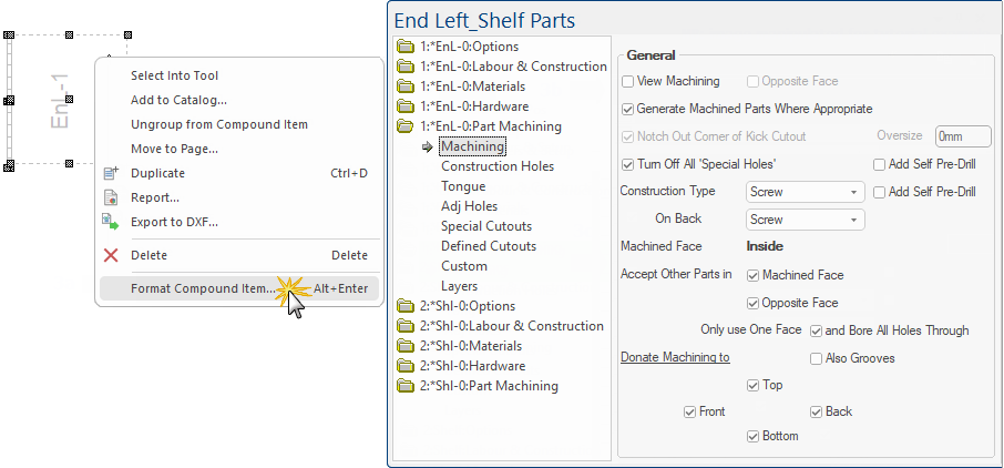
You can create a compound item and further customise individual parts, before or after adding the item to your library catalog.
For this step, we will simply create a compound item so that we can see the options available.
You can use filters available on the View Options [F9] properties to restrict viewing.
In the following example, we have used the Visibilities page to isolate the different sections of the part.
You can filter to restrict viewing to just the machining of interest (a layer, a depth range, routing or holes only, etc) on the Machine Options page.
In the following example, we have turned off the 'Border' layer (which now displays in black).