CabMasterPro User Guide
Callouts allow you to create a zoomed and cropped portion of a view. They can also include dimensions and notations for a greater level of detail and can be used per drawing.
There are 3 main types of Callouts :
Elevation callout
Dimensions etc cannot be added to an elevation directly on the plan view but you can add these for display on the plan by using the Breadcrumbs Bar to go into the Elevation View of the wall/cabinets placed on plan (see Annotating the Elevation Tutorial) or Edit Callout (discussed below).
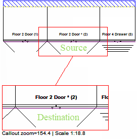
Plan callout
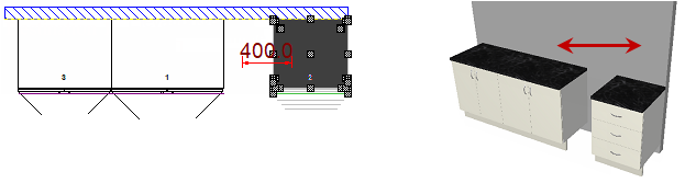
3D callout
See Camera View Items Tutorial as creating a 3D callout is done differently i.e. uses a camera view which allows for the placement of a specified portion of a 3D view item to be cropped and any changes on the plan are immediately reflected in the camera view (3D callout) e.g. open doors or move cabinets etc.
Use the Callouts Property Sheet by using right click menu, for example, to Format callout.
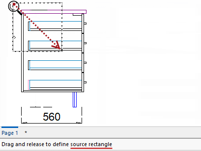
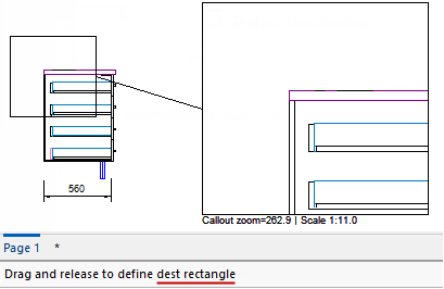
There are two steps to defining a callout i.e. create a source and destination.
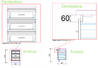
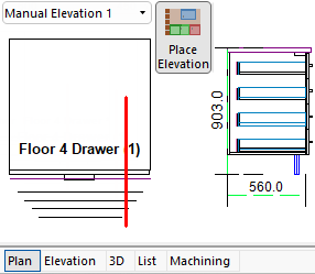
For this tutorial, you first need to create an Elevation. To illustrate we are going to add a callout to the Elevation view of a Floor 4 Drawer cabinet.
Create an Elevation
Simply place a cabinet on the Plan. Then select the Plan Tools Elevations tab to add a manual elevation (no wall is required).
Create a manual elevation by clicking on the Add Manual Elevation Line ![]() command button and then drag a line between two (2) points.
command button and then drag a line between two (2) points.
Then (1) select the Elevation (as per drop list), (2) click on the Place Elevation command button and (3) click on plan to place.
 command button on the Annotate menu tab, then...
Callouts can be selected after placement for removal, formatting and/or editing using the Breadcrumbs Bar or by ;turning on the Select command.
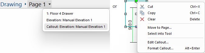
The style and appearance of callouts can be customised either before or after placement by selecting the 'Format Callout' option.
To add annotations such as text and extra dimensions, select the 'Edit Callout' option.
Click to view selected callout and Clear/Delete option
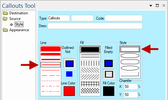
The colours of lines, style (outline shape) and fill style/colour and visibility of lines can all be customised...
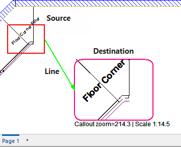
At the beginning of this tutorial the appearance/style is a simple black/rectangle format for Source, Destination and connecting Line. The options allow you to...
The Style page for both Destination and Source have the same controls as the Rectangle Tool.
Source
Here we have changed the Line the colour to red and a thicker width but left the Style unchanged.
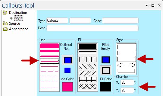
Destination
Here we have changed the Line the colour to pink and a thicker width.
The Style of the rectangle has also been changed to a chamfered corner and the X:Y of this has been changed to 20%.
For more on the relevant Line page options see Line Page Properties.
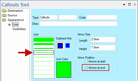
Line Appearance
Here we have changed the Line the colour to green and a thicker width.
We have also added Arrows at end of lines.
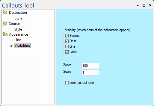
For more on the relevant Visibilities page options see Tool Properties.
Visibilities
Callouts can be annotated, using the commands on the Current Item Editor. Simply Edit Callout to add any of the following...
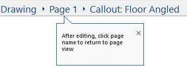
To exit the callout and return to page view, simply click on the page name.
Dimensions etc cannot be added to an elevation directly on the plan view but you can add these for display on the plan by...