CabMasterPro User Guide
To access the Miscellaneous Settings, simply click on the icon on the main menu.

Click to Expand
Click to Expand
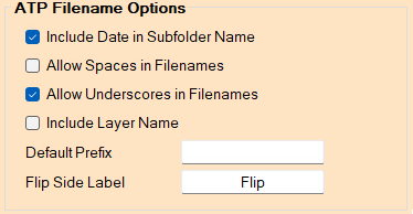
Include Date in Subfolder Name - Whether the current date should be included if/when creating subfolders.
Allow Spaces in Filenames - Same as the Output Option on the Machine Setup > Labels & Output tab.
Allow Underscores in Filenames - Same as the Output Option on the Machine Setup > Labels & Output tab.
Include Layer Name - Whether the layer name is included the filename of outputted files when nested.
Default Prefix - Any prefix to be applied to the filename of outputted files when nested.
Flip Side Label - If 6th face machining is enabled, this text will be included in the filename to indicate to the user that this file is to be used for machining the flip side of the board.
Click to Expand
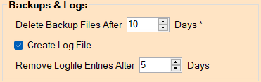
Delete Backup Files After 'x' Days
This refers to the backups created by making changes in this program. By default, this is set to 10 days. To disable, set this option to 0.
Backup files are located in the Backup subfolder of the EzyNest application being used (as specified on the main menu).
It will only delete the files when the CNC-Config program is run after the 'x' days has been reached (and during the process of creating backups of other files).Create Log File
By default this option is enabled. If ticked, a detailed log file is created to show the detailed activity of the user.
The log file will be created as "CNC_Config.log" in the same folder as the CNC-Config program itself.
Remove Logfile Entries After 'x' Days
By default, this is set to 5 days. These entries are removed from the top of the logfile (i.e. the oldest entries) as soon as CNC-Config is started.
Click to Expand
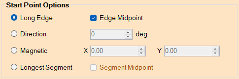
Adjust where start points are automatically located for routing offset toolpaths i.e. this sets the location for where the tool will enter the toolpath.
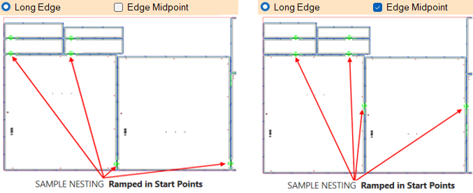
Locate the start point at the start of the longest edge of the contour. If Edge Midpoint is checked, the start point will be placed at the midpoint of the longest segment.
Example
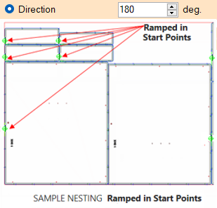
Define a direction used to locate the starting point. The direction is defined in degrees relative to the drawing origin.
Example
The start points are placed on the perimeter of the part based on a direction in degrees (with zero being to the right of the nesting).
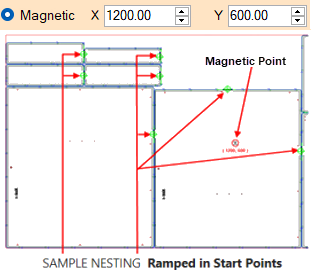
Enter a specific point and the start points will automatically be placed as close to the defined point as possible.
Example
The chosen magnetic position point (e.g. X 1200 Y 600) is normally shown on the nesting.
Locate the start point at the start (corner) of the longest segment of the contour. If Segment Midpoint is checked, the start point will be placed at the midpoint (center) of the longest segment.
Click to Expand
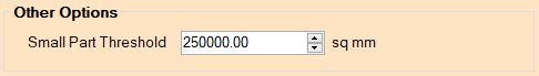
If a part to be machined has its surface area smaller than (or equal to) the size specified by this value, it will be classified as a 'small part' and will therefore have the Small Part Strategy applied to it for machining (instead of the strategy selected on the Define Layers window, in the Strategy column).
Changes are saved on this screen only when the user clicks Save, otherwise changes are abandoned if the user clicks Close, which returns you to the main menu.
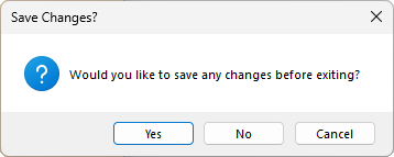
If the you have made changes and Close without saving first, you will be asked if you want to save before exiting the current window.