CabMasterPro User Guide
In This Topic
    CNC Machine Setup
    In This Topic

    To access the Machine Setup, simply click on the icon on the main menu.

    Click to Expand

    Click to Expand


     Machine tab

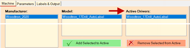
    The Machine tab allows the user to select a make/manufacturer, model and active driver of their CNC machine.

    These selections must be made before setting the Parameters etc, which are dependant on make/model.
    Click to Expand

    Click to Expand

    Add/Remove

    EzyNest cannot work correctly without having the Manufacturer/Model option set.

    You can Add and Remove from the List of Active Drivers. The Save/Continue button will apply the change without closing the current window.

    The current Active Driver will always be displayed bottom/left of the current window.
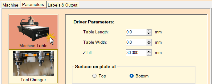
     

     Parameters tab

    Machine Table

    The Machine's Table sets the size of the CNC machine. This is not always required, as this is CNC-dependent.

    Click to Expand

    Click to Expand

    The Surface Plate option determines from where the machine calculates the vertical position of the board. This is most commonly set to Bottom, but there are some machines that require it to be set to Top.

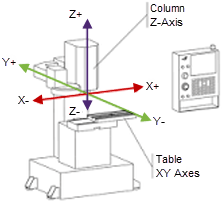
    The Z Lift relates to the up and down movement on the Z Axis (see diagram).

    WARNINGOnce the Surface Plate option has been set by a technician, it must not be changed.

    It is a dangerous setting to change and a warning is displayed if the option is changed between Top and Bottom. If the user is not explicitly sure about this, do not change it, otherwise they risk causing physical damage to the CNC machine.
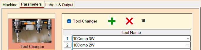
    Tool Changer

    The Tool Changer screen will allow the user to set which tools are in which positions in the CNC machine's tool changer (sometimes called the turret).

    Click to Expand

    Click to Expand

    Just as with the Strategy Configuration window, extra rows can be added or removed by pressing the  and  buttons. The bold black number alongside shows the number of positions available in the tool changer.

    A specific row doesn't require selection to remove it. Pressing the  button will just remove the last row from the bottom of the list.

    For more on recommended tooling, see Tooling for CNC Machining.
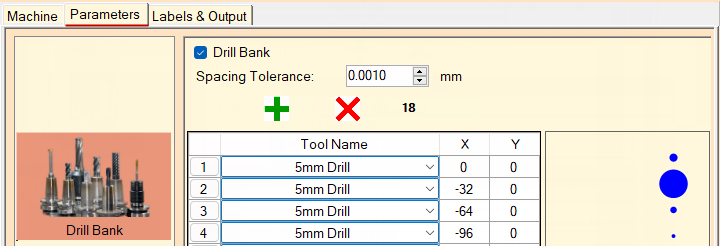
    Drill Bank

    Drill Bank controls the options for the drill bank, including the option to set the X and Y positions of the drill positions in the machine. 

    Click to Expand

    Click to Expand

    Like the Tool Changer, discussed above, extra rows can be added or removed by pressing the  and  buttons.
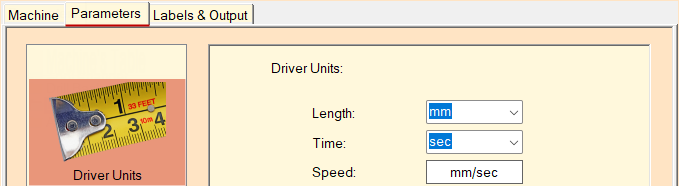
    For recommendations on Drill Banks, see Tooling for CNC Machining.

    Driver Units

    Driver Units allows you to set select the units that will be used to measure Length, Time and Speed.

    Click to Expand

    Click to Expand

    For ALL drivers it is particularly important to set the Driver Units to the units the driver is expecting, usually mm/sec.

    Notes and Examples

    Driver Units Speed is usually mm/sec even when you use different units in the Strategy, Tool or Drive Setup. Feeds convert 'Driver Units' as it hands the numbers over to the driver.

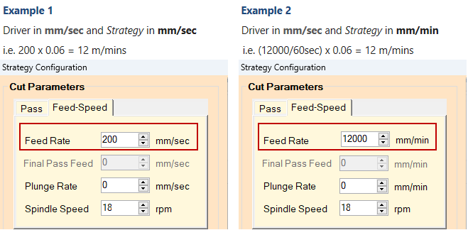
    Both the SCM and the Biesse driver (and perhaps others) require GCode in m/min which is NOT one of the available choices. Therefore the driver does a conversion from mm/sec to m/min as per Example 2.

    Advanced

    Advanced provides the options of machine resolution (minimum available steps per mm in each axis), and angles.
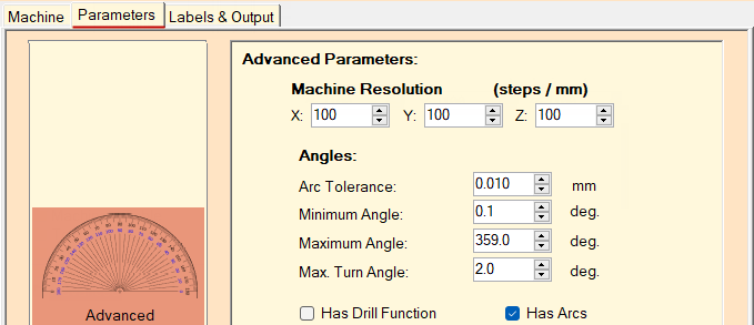
    Click to Expand

    Click to Expand

    Machine Resolution 

    • X-axis allows movement “left” and “right”
    • Y-axis allows movement “forward” and “backward”
    • Z-axis allows movement “up” and “down”

    Diagram of XYZ Axes

    Arc Tolerance

    Arc tolerance is used to vary a point along the path of an arc.


     Labels & Output tab

    Label Options

    Create Labels check box must be ticked if you need labels to be printed to identify each nested part. Labels can be designed using the Label Designer program (included with EzyNest). If left unticked, this will not prevent you nesting the job but no labels will be produced.

    Label Design Used allows you to select a label design (.lds file) created by the Label Designer application.

    Label Format Used is the required stationery created in Label Maker application.

    The Open buttons provide quick access to both applications.

    Click to Expand

    Click to Expand

    Example

    A generic design may look similar to this...

    Output Options

    Output Path:

    This will be the location where the files created during nesting will be located after the nesting is complete.

    Output File Extension:

    This is set by technical support pertaining to your machine and should not need to be changed.  

    NC files are typically associated with Woodtron machines and contain cutting instructions.

    Biesse machines have three types of cutting instruction files i.e. CIX, ISO, XNC.

    Flip Side Label Prefix:

    If 6th face machining is enabled, this text will be included in the filename to indicate to the user that this file is to be used for machining the flip side of the board. This option is also available in Miscellaneous Settings.

    Output Filename:

    Over type the "Rename_This" value to provide a Job Name. This will be the beginning of the filename for the files created during the nesting process. The material type is normally added to the end of this name. With most machines it is best to avoid any special characters and spaces.

    For example, if the Output Filename is “My Drawers”, and the material is “16mm Carcase White”, the GCode file created would normally be called “My Drawers_16mm Carcase White_001.nc”, where 001 is the sheet number.

    Spaces and Underscores:

    Turn on/off whether to allow output filenames to include spaces and/or underscores. These options are also available in Miscellaneous Settings.

    Some machines, such as Biesse, do not like a comma, underscore, dots or dashes in the filename and have a limit on its length.

    Pic Settings

    These options can also be located in EzyNest under Setup > Preferences > AutoTP tab.

    Alternative Compass Orientation

    This option allows the label image files to rotate (to suit the position of the parts on the nest) - see Label Rotation Settings.

    Pics Option

    This should be set to 'Include Job Name' to ensure the pics/xml file is in the  same folder at CNC files and is using the same name. This enables Machine View to work with EzyNest.

    Colours

    When you Generate Nests in Machine View the colours provide detail to the display.

    This example shows the part Number Circle in blue with the Text in white. The Part Outline is red and Plate is displayed in grey.