CabMasterPro User Guide
For quick links to more information, click on  the controls or another category/page.
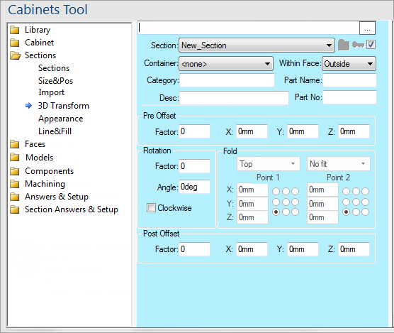
To find out the property names for these controls, see the Section 3D Transform page under the Formula Reference.
Once a section has been sized and placed initially with Section Size and Pos, this transform page allows you to offset a section then rotate about an axis, then do another (post) offset.
You can therefore do things like swing doors open and slide drawers out, using the offset properties. For example, you can move a section onto a defined hinge line, so that you can attach as a flap.
Once you define a hinge line, you can also do a 3D rotation of this section around that hinge line. This lets you do things like folding up a box made from multiple sections hinged onto one another.
The drop lists allow you to select the required fold options.
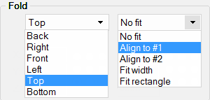
The first combo selects the face of the container section (e.g. “box”) to use as a reference face to specify coordinates (to position the section called “flap” in this example).
Click to Expand
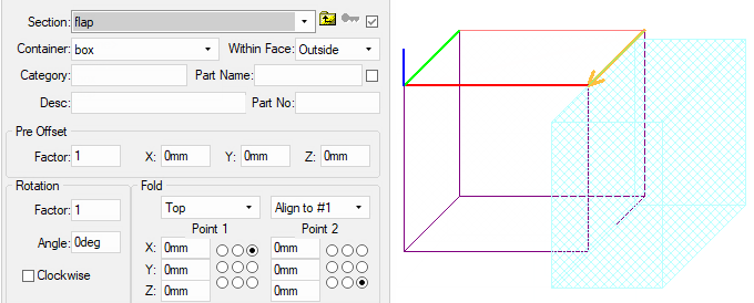
The rest of the Fold group box specifies the start (Point 1) and the finish (Point 2) of the fold line, which is shown in gold with an arrow pointing from start to finish.
In this example, we have chosen the “Top” face in the face combo, and so its nominal rectangle is outlined with RGB lines.
While you are viewing the 3D Transform page, you can see additional red, green, blue (RGB) and gold lines.
The section you are viewing is placed and rotated based on these lines. The RGB lines are for the reference X, Y and Z axes. The gold line with the arrowhead on it is there to show you your chosen hinge line for rotations in 3D. The section will be rotated around the specified hinge line, and then positioned and scaled.
Notice there are two red lines and two green lines. The stronger lines are the X and Y axes of the face. The fainter lines are the far side of the face rectangle.
In the above example, the faint green line is situated under the gold line.
Using the right hand rule you can see the blue line is showing the Z axis. (Move the fingers of your right hand from X (R) to Y (B) and your thumb will point to the Z (G) axis.
Finally any Face Offsets will be applied - discussed below.
In the above example, we have selected the right hand edge of this rectangle for the hinge line, using the 9-way radio buttons for Point 1 and Point 2.
Thus the gold hinge line is on the right edge, and when we select “Align to #1”, then the nominal section positioning for the “flap” section is on that hinge line starting at Point 1.
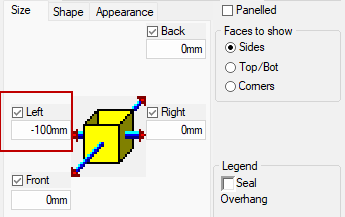
In this example, there is also a Face Recess of 100mm for the flap, which is why it places the face origin of the flap 100mm is along the hinge line instead of exactly on it.
Faces page - Click to Expand