CabMasterPro User Guide
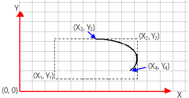
Creates a clockwise elliptical arc from Start to End point, with the ellipse specified by its bounding rectangle.
| SecMin | The X, Y, Z co-ordinates of the min corner of the section which this machining step is inside. |
| SecMax | The X, Y, Z co-ordinates of the max corner of the section which this machining step is inside. |
| JoinMin | The X, Y, Z co-ordinates of the min corner of the section which this machining step is joined to. |
| JoinMax | The X, Y, Z co-ordinates of the max corner of the section which this machining step is joined to. |
| CutSize | X, Y, Z contain the values from this component dimcut1, dimcut2, dimcut3 respectively. |
| FinishedSize | X, Y, Z contain the values from this component dim1, dim2, dim3 respectively. |
| PartID | A name for this step, init as component name, not sent to DXF usually. |
| Layer | The layer name written to the DXF, init as steptype but you should set this to something more meaningful e.g. in EzyNest. In addition, this layer value can be prefixed by + - or ~. The prefix is not sent to the DXF, but is used to indicate notches, where two steps are combined. A + is for combining two steps by adding the paths together. This can extend the outer shape. A - is used for subtracting or creating a notch. And a ~ is for flap donor steps. (See Flaps In Remote Components) |
| Group | The group name written to the DXF. Default value is ungrouped. Different groups will be nested separately, so for example a DXF with some ungrouped machine steps and some steps in group 10 and others in group 20 will nest as three separate parts. |
| ColorIndex | The color used in the DXF (usually unused by Machining but very helpful for viewing). Colors are defined by Voloview DXF viewer. (See also DXF Layer Colours):
|
| Min | XY coordinates of lower left corner of a rectangle. |
| Max | XY coordinates of upper right corner of the rectangle. |
| Start | XYZ: location of start of the machining step. |
| End | XYZ: location of end of the machining step. |
| Depth | Depth of the of the cut/drill. |
| RepeatCount | X: Whole machine step is repeated this many times. Y: If this is >1, then do a rectangular array of repeats. |
| RepeatOffset | XY: Offset vector between copies (for linear repeats). For arrays of repeats, X is the X offset and Y is the Y offset. Here's a little example of a BorderDeco step repeated in a 3x2 array: |
| ProfileFolder | Folder for QPFs, default BitmapFolder, can be relative. |
| ProfileName | Name of the profile. The default extension is ".qpf". An array of names is allowed, if defining multiple profile edging. |
| ProfileEdging | Array of edge treatments. See Edge and Pocket Profile Tutorial : Defining a Profile |
|
Entry is a yes/no determining whether the area inside the machinestep is to be removed. Applies to contours (closed polylines only). |