CabMasterPro User Guide
To access the 'Nesting Options' window, simply click on the main menu Nesting Settings icon. This window allows the user to set how the nesting will be produced.

Click to Expand
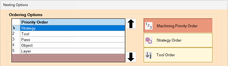
The Ordering Options contains three sets of options that can be adjusted, selected by the three (3) buttons to the right of the Up/Down arrows used to move selected line item up/down in the displayed list.

This determines the order of which all toolpaths will be machined.
The recommendation is for the Priority Order to be set as the following (as per image above).
Strategy - The strategy that was used to create the toolpath.
Tool - The tool used in the strategy.
Pass - The cutting pass used by the toolpath.
Object - The object (part) that is being cut.
Layer - The layer that was used that had the toolpath applied to it.
This means that the cuts will be sorted based on the strategy used, attempting to process all toolpaths on the plate that use the same strategy, before then changing tools to move to the next strategy. It will then try to complete all passes required on a part before starting a cut on the next object/part.
This is a recommendation only, as this is initially set in consultation with your machine technician and changes should be done with extreme care as it may cause damage to your machine.
Note that the G1
settings are not necessarily the same as the ATP - see Moving Nested Parts and Producing New GCode.

This option determines which item is more important, when determining the machining order of toolpaths.
Usually, drills and island fill are machined first, before engrave and offsets. This is because engraves and offsets will machine toolpaths into the board, which cause the vacuum on the CNC bed to lose suction (due to the holes cut into the board). Therefore it is best to have these strategies machined last.

This option determines which tools are considered more important to machine with first.
Again, drills would usually run first, before moving on to the offset tools (because of the vacuum issue).
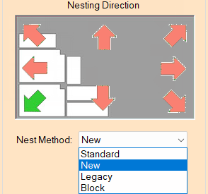
The red arrows in the Nesting Direction diagram can each be clicked on to set the origin point, which is where the parts will start being placed on the plate when nested, and then surrounding that section.
The green arrow shows the currently-selected position of the part shown in white. The application has set the parts starting from the selected position and puts all other parts surrounding it.
Click to Expand
Select one of the methods from the drop list. These are...
Standard
This is the default algorithm and has been present since EzyNest v4. This method takes into consideration the actual shape of the part while figuring out where to position each part on the nest.
New
This nesting method allows EzyNest to automatically recognize contours that are selected as nesting “obstructions” and will nest around these obstructions. This provides a very simple way to avoid clamps on the machine or to avoid a section of the material that is not good for nesting, such as knots or other defects in a solid wood panel. It also takes into consideration the actual shape of the part while figuring out where to position each part on the nest.
Legacy
This is the original nesting method that was used with older versions of EzyNest. (The 'Standard' and 'New' nesting methods have since been developed for better efficiency). This method takes into consideration the actual shape of the part while figuring out where to position each part on the nest.
Block
This method is designed to be used with squares and rectangles only. Despite the shape of the part (i.e. triangle, circle, etc), the Block method determines the position of all parts on the nest by assuming that all parts are either square or rectangular.
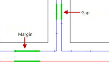
The gap is the distance that will be between the outer-most toolpaths of adjacent parts i.e. part placement from the edge of the sheet.
The margin is the distance from the edge of the plate (red line) to the centre of the toolpath of the nested part (blue line) i.e. how much distance to add between parts. For the purpose of calculation, the edge of the plate (red line) is the centre of the tool if there was a margin of zero.
Gap, Margin: Overall part dimensions when nesting include any external toolpaths allowing nesting spacing parameters to be very small or even 0.0 to maximize material usage. See also Setup Sheet Size and Part Spacing in ATP.
This is the direction that the grain runs on the sheet of material, if it is grained material.
Set this to X Direction if the grain runs horizontally (along the long edge) when the sheet is viewed in a landscape/horizontal orientation, otherwise set it to Y Direction.
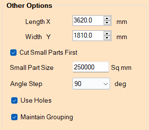
This relates to the sheet of material where Length X (long edge) and Width Y (short edge) when viewed in a landscape/horizontal orientation.
Tick this checkbox if you would like to have small parts cut first. A Small Part is any part that has a surface area that is less than the threshold defined in Miscellaneous Settings.
This is the same as the threshold defined in Miscellaneous Settings.
If a part is allowed to rotate, the nesting algorithm may rotate that part by the angle specified here in order to find a suitable position for it on the nested plate.
If a part has a large cutout in the centre of it, that large cutout would normally be discarded. The Use Holes option allows smaller parts to be nested inside the centre of those larger parts’ cutouts.
Tick this checkbox if you want to treat grouped objects as a single reference for the priority orders.
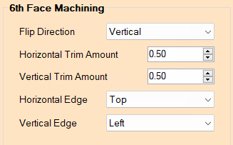
These options are only enabled if using EzyNest v7 or later.
The direction the material will be rotated when processing 2 sided geometry.
The thickness of material trimmed off the horizontal edge of the material to create an accurate registration surface for flipping the material.
The thickness of material trimmed off the vertical edge of the material to create an accurate registration surface for flipping the material.
Select the Top or Bottom horizontal edge to trim.
Select the Left or Right vertical edge to trim.
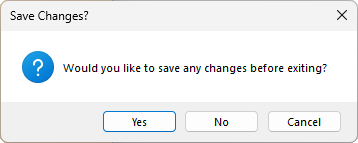
Changes are saved on this screen only when the user clicks Save, otherwise changes are abandoned if the user clicks Close, which returns you to the main menu.
If the you have made changes and Close without saving first, you will be asked if you want to save before exiting the current window.