CabMasterPro User Guide
It is a relatively common requirement as part of your production process to alter the position of parts on a plate after it has been nested and to produce new G-code to reflect these changes. This is quite a simple process.
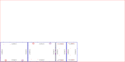
In the example, a pair of grained doors and drawer bank have been nested using the standard method - by importing a .dxt file in the ATP Setup  .
.
Example of Nest using Standard Method
For more on nesting using the standard method, use the above link.
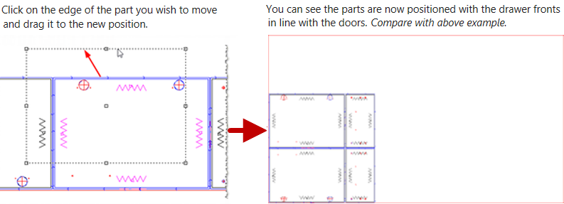
If you need to move the parts around, for whatever reason, after they have been nested, the simplest method is to click and drag.
You want to move the parts around on the nest to minimise material wastage, or to fit on a spare sheet of material. In this example, we are moving the parts to have the grain on the drawer fronts match the doors.
Another way to move parts is to simply left-click on the part you wish to move and use the arrow keys on your keyboard. Holding down the Shift key while pressing the arrow keys makes the part move faster!
Although this method is quite simple, it might not be putting each part in the most efficient position alongside other parts.
There are two other options available, Precision Input Center [F2] and Dynamic Nesting, that moves parts around the plate while complying with specified settings.
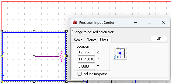
Click on the part to select and then hit F2 to open the Precision Input Center. As shown, you can change the scale, rotate or move the selected part.
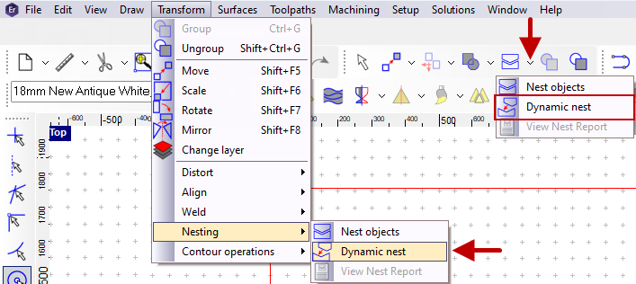
Click on the Dynamic nest command (as shown EzyNest23) which can be located on the Edit toolbar (which also contains the white Select arrow ) or on the Transform > Nesting menu.
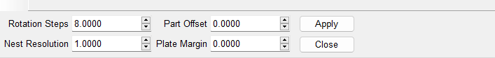
When using Dynamic Nesting, an options panel appears at the bottom left of your screen, as shown and you will need to set these options before moving any parts around on your plate, which will be discussed next.
Specifies how many snapping points the part can rotate to, based on 360° in a circle.
For example, if you would like your part to be able to snap to a rotation of 45° (360 ÷ 45 = 8 rotation steps in a 360° circle) so the Rotation Steps is set to 8.
This must be a whole number, decimals are not permitted.
Recommendation : If you are modifying a nest of cabinet parts, it is recommended to rotate in 90° increments (i.e. 360 ÷ 90 = 4), so Rotation Steps would be set to 4. However if you are nesting ACM, it depends how many angular parts you have in the shape you are moving. You could rotate in 15° increments ( 360 ÷ 15 = 24) so Rotation Steps would be set to 24.
Imagine the nesting plate is covered in a grid, and each part must snap to the grid’s lines. The Nest Resolution is the distance between each line of that grid. The higher this number is, the longer it will take to position the object. This value can only be between 1.0 and 10.0.
Recommendation : The default option for this is 1.0 - it is recommended to go no higher than 3.0
The same as Gap in the ATP Setup. This is the minimum distance between each part when nested on the plate.
Recommendation : No less than 2.0mm. CabMaster Software™ typically suggests a lead in and lead out that would be between 0.5mm to 1.0mm from the edge of the part, so leaving an offset of 2.0mm should keep any two parts a suitable distance apart.
The same as Margin in the ATP Setup. This specifies how far the parts will be from the edge of the plate. Using 0.0mm leaves the centre of the tool right on the edge of the plate.
Recommendation : This value really comes down to your own personal preference, as well as the quality of the edge of the material you will be machining. As specified above, a plate margin of 0.0mm is suitable, but if the edge of the sheet you are machining is chipped around the edges, you would need to increase the margin to clear this distance. A margin of 5.0mm is very common. However, your ATP will also have a margin set which was used to create the current nest, and it would be worth using that same margin value.
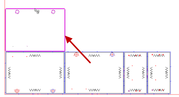
After you have set the options, click Apply, then click on an edge of the part you wish to move, which will then make the part turn pink.
Click on the edge of the part again and move your mouse cursor to the area you want to place the part. The pink outline of the part will follow your mouse and rotate based on the Rotation Steps option above. When the part is in the correct position, click to lock it in place.
Do not click and drag when using Dynamic Nesting. Just click and let go, and the pink outline of the part will follow the mouse!
To stop this feature, simply click on the Select command (white arrow on same toolbar as Dynamic Nest command).
Example of Pink Outline
In the image, the part on the lower right has been selected using this method and is about to be placed in the space above, indicated by the red arrow and pink outline.
Before you produce your new GCode file, there is one very important step to ensure you avoid any potential damage to your machine. You need to compare the Surface setting is the same in both the ATP and the Define Plate options.
ATP Setting
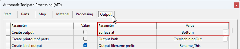
Take note of the Surface at value but DO NOT change this option. In this example, it is set to 'Bottom'.
In EzyNest23, this option is located on the Output tab (shown above). In older versions of EzyNest, it is located on the Ordering and Nesting tab.
Once this option has been set by a technician, it must not be changed.
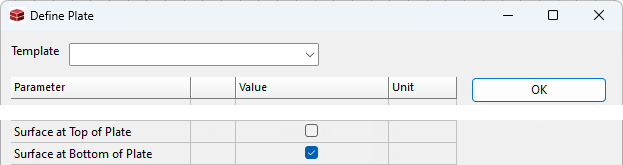
Define Plate Setting
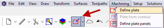
Open the Define Plate options dialog from either the toolbar or Machining menu, as shown.
The Surface setting must be the same as selected in the ATP (example above). If these two options do not match, you run the risk of the machine drilling right through the material and into the machine bed.
Click to Expand
After you have finished repositioning the parts on the nest and set the Surface option above, you will then need to create new GCode to send to your machine.
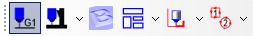
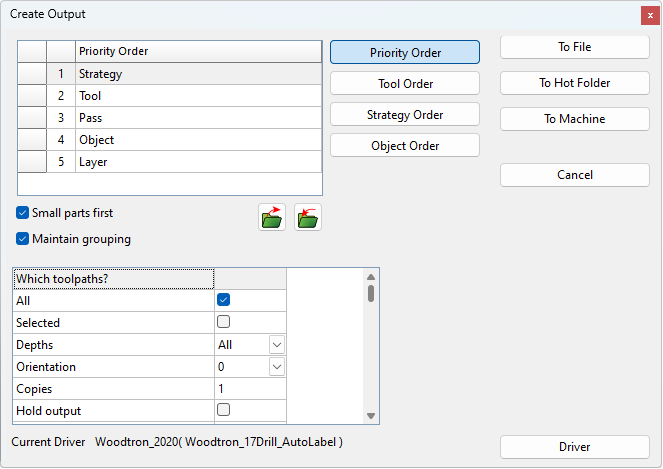
On the Output toolbar (shown), press the G1 button (located near the ATP button). This will open the a dialog, as shown.
This List shows the priority order for the option selected by using the Order buttons located to the right of this list. This determines the order of which all toolpaths will be machined. For more on Ordering options and how to move items in the list see the ATP Output tab topic.
The recommendation is for the Priority Order to be set as STPOL
Strategy - The strategy that was used to create the toolpath.
Tool - The tool used in the strategy.
Pass - The cutting pass used by the toolpath.
Object - The object (part) that is being cut.
Layer - The layer that was used that had the toolpath applied to it.
This means that the cuts will be sorted based on the strategy used, attempting to process all toolpaths on the plate that use the same strategy, before then changing tools to move to the next strategy. It will then try to complete all passes required on a part before starting a cut on the next object/part.
It is also worth noting that the ATP, that was used to create the current nest, will have a priority order set on the Output tab.
The G1 settings are not necessarily the same as the ATP. For purposes of consistency, set the priority order in the G1 settings to the same as is set in your ATP.
Click this checkbox if you would like to have small parts cut first. A Small Part is any part that has a surface area that is less than the threshold defined in the EzyNest Preferences - (select from the Setup menu Preferences > Initialization > Small Size Threshold)
Click this checkbox if you want to treat grouped objects as a single reference for the priority orders.
In this section, it is important that All Toolpaths is ticked. No other options in this box should be changed.
Once you have set the required options above, press the To File button. Enter a filename for you GCode file and press Save.
Once you have completed this process, you can use your usual method to move the G-code file to your CNC machine and run the job as normal.