CabMasterPro User Guide
To locate information about any option or another tab,  click on the area of interest.
If you make any changes to the currently selected ATP (displayed on the Start tab) and you want them to be applied for all future jobs, then ensure that you click on the Save ATP file before closing.
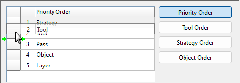
This list title changes depending on the selected Ordering Options. In the above image, the list displays Priority Order.
To move an item in the list, simply click on the grey box on the left (shown) and drag up/down. Green dots will appear to aid in placement.
These buttons change the Order List discussed above, allowing you to change the order of different options.
This determines the order of which all toolpaths will be machined.
The recommendation is for the Priority Order to be set as the following (as per image above).
Strategy - The strategy that was used to create the toolpath.
Tool - The tool used in the strategy.
Pass - The cutting pass used by the toolpath.
Object - The object (part) that is being cut.
Layer - The layer that was used that had the toolpath applied to it.
This means that the cuts will be sorted based on the strategy used, attempting to process all toolpaths on the plate that use the same strategy, before then changing tools to move to the next strategy. It will then try to complete all passes required on a part before starting a cut on the next object/part.
This is a recommendation only, as this is initially set in consultation with your machine technician and changes should be done with extreme care as it may cause damage to your machine.
Note that the G1
settings are not necessarily the same as the ATP - see Moving Nested Parts and Producing New GCode.
Tool Order
This lists the priorities of the tools used in the current job. It is recommended to have drills used before compression cutters to avoid losing suction as the machining progresses. This list has a “Use” checkbox, which will disable that particular tool from being used in the job if it is unticked.
Strategy Order
This lists the priorities of the strategies used in the current job. It is recommended to have drills used before offset strategies to avoid losing suction as the machining progresses. This list also has a “Use” checkbox, which disables that particular strategy from being used in the job if it is unticked.
Object Order
This list contains a list of options to determine which the order in which each object/part it should be machined, and a “Use” checkbox column that allows only one checkbox to be ticked. Here you can select whether it should select the next object that would take the shortest machining time, or if it should select the part in rows or in columns, or if it should select objects from the inside/middle of the plate and moving outwards, or from the outside of the plate and moving inwards.
If this checkbox is ticked, G-code files will be produced when the job is nested.
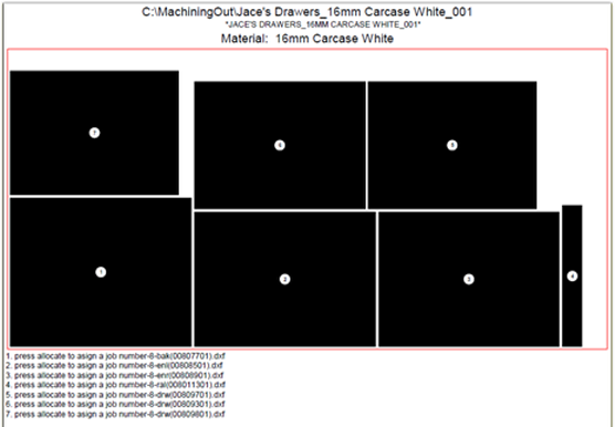
This option will print a layout of the nested plate, as one plate per A4 sheet. It will be sent to the printer selected at the Printer option.
Example
If you need labels to be printed to identify each nested part, tick this checkbox. Labels can be designed using the Label Designer program (included with EzyNest).
See Processing tab where you select a Label Design (.lds file) and Label Format
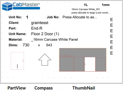
Examples of Labels
A generic design may look similar to these label examples. See
This option will put each individual part on a sheet of its own, with no other parts on that sheet. For example, if you have 10 parts to be nested, it will put 1 part on each sheet, and use 10 sheets to complete the nesting.
If this is ticked, it will group all the output files together (including G-code and labels) and put them in a folder of their own.
This is the side of the material (either Top or Bottom of plate) that the machine will determine as its zero point on the z-axis.
This is also specified on the CNC Link Machine Step > Parameters > Machine's Table.
This will be the location where the files created during nesting will be located after the nesting is complete. If the Create Output Subdirectory checkbox is ticked, then the folder containing all the output files, including print files, will be in a folder inside this Output Path folder.
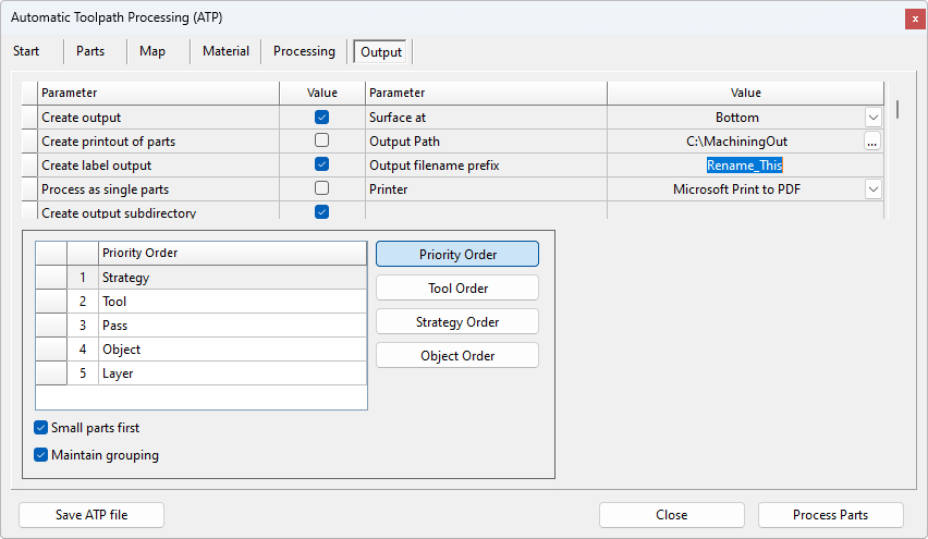
Example
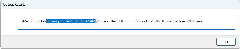
In this example, the Output Path is 'C:\Machining', the Output Subdirectory is highlighted (format is 'DrawingName_mm_dd_yyyy_time') and the Output filename prefix is 'Rename_This' (which normally would be changed before processing).
Click to view contents of Output Subdirectory
Over type the "Rename_This" value to provide a Job Name. This will be the beginning of the filename (and subdirectory/folder name) for the files created during the nesting process. The material type is normally added to the end of this name. With most machines it is best to avoid any special characters and spaces.
For example, if the Output Filename is “My Drawers”, and the material is “16mm Carcase White”, the GCode file created would normally be called “My Drawers_16mm Carcase White_001.nc”, where 001 is the sheet number.
These can also be defined on the CNC Link Machine Setup > Labels and Output tab.
If the Create Printout of Parts checkbox is ticked, it will be sent to the printer selected here.
Tick this checkbox if you would like to have small parts cut first. A Small Part is any part that has a surface area that is less than the threshold defined on the CNC Config Miscellaneous Settings.
Tick this checkbox if you want to treat grouped objects as a single reference for the priority orders.