CabMasterPro User Guide
There are a number of ways repetitive machine steps can be handled within CabMasterPro.
Some machine steps have the ability to repeat their shape into a nested set of shapes.
For example, Border steps have two rows "NestCount" and "NestOffset" which let you repeat the shape with nesting like this: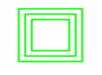
Here we have a NestCount of 2, giving us the defined border plus the two inner shapes, nested by the (x,y) amount provided in NestOffset. Negative NestCounts suppress the main shape, so -2 would be just like 2 but with no outer shape. Negative offsets make the shape grow instead of shrink.
NestCount is supported for Border, BorderArch and BorderDeco steps, but is not supported in the Border steps with Veins and Windows.
You can create the same effect for the unsupported steps by using NestOffset, which still alters the defining rectangle. Thus a machinestep sequence can be used to create nested shapes for steps if necessary by formula controlling NestOffset using the sequence number.
Most machine steps have the ability to repeat themselves completely, making a row of patterns or even a rectangular array.
For example, the step above could be repeated 3 times with a specified offset to give this: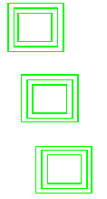
In this case, the bottom shape is the defined step, and the two above are the repeats, with offsets of X=-25 Y=150 (that is, move left a little and up 150, the square is 100 x 100).
Specifying a repeat count with an X and a Y creates a rectangular array of shapes instead of a row of shapes.
Sometimes this is not enough - you may actually need the elements of a sequence to be different in one of the fields that is normally common.
For example, you might want different tools or different depths for the cut or different joinsections or whatever. In this case, you really need a set of individually defined machine steps. When the steps are numbered, like ShelfHoles1, ShelfHoles2, ShelfHoles3,... then you can use the # and @ operators to pick up the number and determine other behaviour with formulas. Thus, the steps in a sequence can behave differently based merely on their names - even if the individual steps in the sequence are copy/paste clones of the same step.
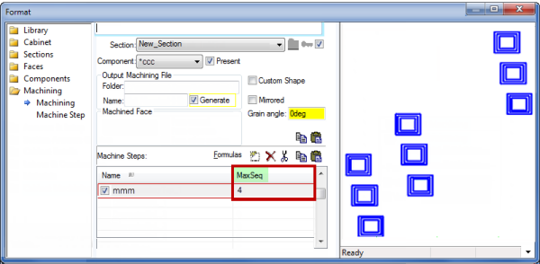
To support this more efficiently, there is a MaxSeq field in the MachineSteps list. By default, this is set to zero, giving just the defined step. But if you set it to a number bigger than zero, the whole step is repeated, just as though you had copy/pasted it.
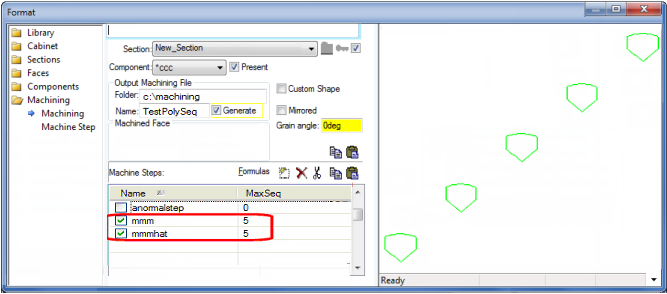
Here's an example:
The step mmm has MaxSeq=4 above. This means it is repeated in full 4 times. The individual steps have names mmm[1], mmm[2], mmm[3] and mmm[4]. Notice in the preview on the right there are only 3 steps visible - 1, 2 and 4. Step mmm[3] is missing. This is because we put a formula behind the step present checkbox like this: not #=3 (The # extracts the 3 from the name mmm[3] and the formula not #=3 makes the third step disappear).
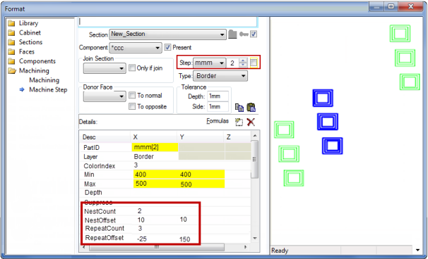
Notice that all steps in the sequence are highlighted in the preview pane. But when we click on the Machine Step tab, only the currently selected step in the sequence is highlighted, like this:
Notice the step combo (circled) now has a spinner control to the right, letting us select 1,2,3,4 since MaxSeq is 4. Here we have selected 2 and step 2 only is highlighted in the preview pane. As you change the spinner, the formula controlled values (like the Min and Max coordinates of the square) will change, simply because they are formula controlled referencing the name. For example, Min.X is 400 in the screen grab above. It has the formula 200*@ which picks up the 2 from the grid's parent context, mmm[2], giving 200*2. As you change the spinner to select mmm[3] etc, you will see the values in grid update to show the correct value for the current step. It is important to understand, however, that there is only one step defined in your data, so changing the data in the grid will make the change for all steps of the sequence.
Using MachineStep sequences, you can create steps which have different joinsections or present checkboxes, as well as different layers, depths and so forth.
MaxSeq itself can be formula controlled, making it very efficient to set up just the number of steps you need - even if there could be 20 shelves in a cabinet, you can set up so that the common situation with 2 shelves is handled by 2 steps (MaxSeq=2 from a formula).
Also for efficiency, the value MaxSeq = -1 has the special meaning that the step is completely suppressed. This means that it does not even need to be created to, say, check the Present flag, so this is much more efficient than just using a formula in the Present flag.
In the example above, notice that the PartID is mmm[2] for step 2. It has the formula name which just picks up the name of the step. Because it is a sequenced step, the name changes to mmm[1], mmm[2] etc as we move through the sequence. This is why the @ and # operators work. These operators can be used anywhere in CabMasterPro, not just in machining. The # operator just extracts the last numeric sequence from the current context, while the @ operator does the same thing using the parent context. See also Built In Variables
For example, if we have a polyline step instead of a border like above, we might have a formula in the grid behind mmm.point[3].x. For step 2 of the sequence, the name behaves like mmm[2], so strictly speaking, the grid reference is mmm[2].point[3].x. The # operator in this case picks up the 3 from point[3], while the @ operator picks up the 2 from the parent context mmm[2].
When you have two machine steps, it can be useful to refer to values in one step from the other. This can be done by using formulas like MachineStep["abc"].Point[1].Y for example - referring to a different machine step (abc) and looking up the Y value for Point[1] in its entry list.
The same thing applies when the steps are sequenced (ie MaxSeq > 0). Implicitly, the lookup adds the sequence number so we can have linked sequences.
For example, here we have two steps mmm and mmmhat, creating this composite shape: 
. mmm is a polyline with 5 points, and mmmhat is the arc across the top, from Point[1] to Point[5]. The arc center is Point[3]. With both steps having MaxSeq=5, this creates steps mmm[1] to mmm[5] plus mmmarc[1] to mmmhat[5] giving this sequence of shapes:
In this example, we want to use the mmm polyline to provide the positioning of the arc in mmmhat. The screen grab below shows mmmhat[4] since the spinner is set to 4, and double clicking on the Center.X field gives the popup info box showing the formula behind it as machinestep["mmm"].point[3].x
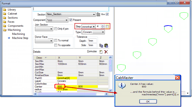
This formula picks up point[3].x from the corresponding step in the mmm sequence. Because we are in step mmmhat[4], the corresponding step is mmm[4], so it looks in that step of the mmm sequence and gives us point[3].x as required. In this way, the arc shaped hats are created for the 5 steps in the mmm sequence.
This example discusses two cabinets (A and B)...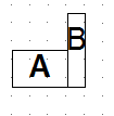
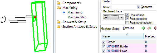
Cabinet "A" donates machining from its Right face (to both 'Normal' and 'Opposite').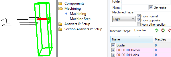
It has 2 machine steps. (1) a 1mm Border to show its' outline and (2) some holes.
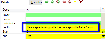
The depth of the holes is formula controlled - "if 0 then Acceptor.dim3 else 12mm".
Cabinet "B" accepts machining from 'normal' and 'opposite'.
If you change the face to "Left" then the holes pick up the smaller depth given in the "else" part of the formula.