CabMasterPro User Guide
For quick links to more information, click on  the controls or another category/page.
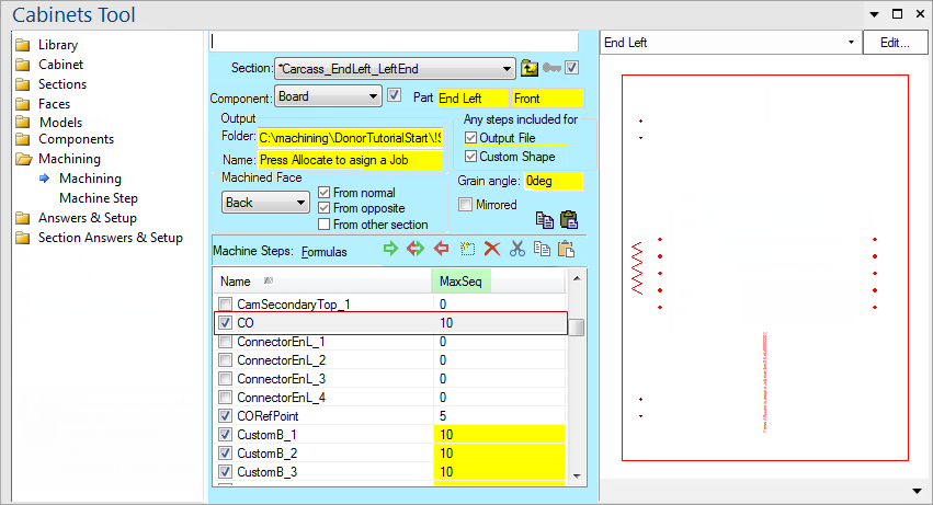
To find out the property names for these controls, see the Machining page under the Formula Reference.
This checkbox determines whether the current component is present. It is the same as the Component Present checkbox in the Components pages. When a component is not present, any machining defined for it will not be generated.
When the quantity is set to zero, the DXF will not be generated. Since the component quantity can be used for other purposes, it can actually contain decimal fractions. The Quantity is rounded to the nearest integer for machining. When greater than one, only one DXF is generated but the (integer) quantity is handed through to EzyNest via the control file (DXT).
Generate the machining DXF's for this component when exporting machining.
Allows you to use this machinestep to generate a custom shape and create a 3D shape from it. See tutorial on Custom Shapes.
If this box is checked, the machine step generated will be a mirror image of the step defined by the Machine Step page. The Preview Pane will show the mirror reversed step, but note that the DXF generated will not be mirrored - the mirroring is handled by the control file (DXT) which carries a mirrored flag. This causes the DXF to be mirrored during the ATP step of EzyNest.
Example
For example, here's an asymmetric DXF:
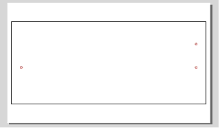
If we set up a DXT to use this one DXF three times - once normally and twice mirrored, then in EzyNest we get this:
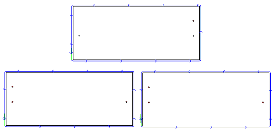
Here, we can see the second and third parts are mirrored - you cannot rotate the original part to get the holes in this location.
When a component is grained (i.e. not allowed to rotate during nesting) this specifies the actual angle of the grain so that it can be correctly aligned in the nest. For example, if the grain is vertical, we would specify this as 90deg and if the board has horizontal grain, the part would be given an initial rotation of 90 degrees for the nest and not allowed to rotate during the nesting.
The folder to write the machining DXF file to.
The filename to write the machining DXF file to.
Copy the entire Machine Step List using the copy button, then you can use the paste button to paste the entire list into another component. You can copy to any component in any section of any cabinet, perhaps elsewhere in the drawing.
These buttons  control the list of machining steps. In order the buttons are:
Double-clicking on a step will go to the Machine Step page.
Switch between showing the values and the formulas generating them in the Machine Step List (discussed above).
We need to specify which face of a section is getting machined. This lets the system determine whether donor steps from other faces might be accepted along with other machining for this machined face. See donor/acceptor calculations. Donor Faces for more information on that. It also allows the views (3D, Plan etc) to display the actual machining. So if we are cutting a rectangle and drilling several holes, they will appear in the views if View Machining is turned on for that view.
Indicates whether to include donor steps hitting the given face. See also: Opposite Face Acceptance tutorial.
Indicates whether to include donor steps hitting the opposite face to the given face. See also: Opposite Face Acceptance tutorial.
Indicates whether to extend the bounds of the acceptor face to include the other section.