CabMasterPro User Guide
For quick links to more information, click on  the controls or another category/page.
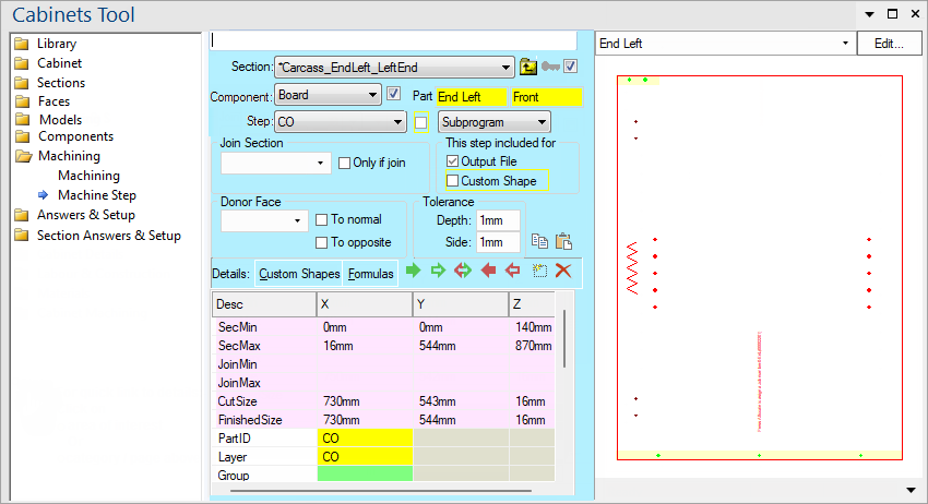
To find out the property names for these controls, see the Machine Step page under the Formula Reference.
Choose the HSection of the current cabinet you wish to set machining for from this drop list.
Go to the parent section of the one selected in the Selection drop list.
Press this ![]() button to import a copy of the machining from the library into this cabinet so it can be customised.
button to import a copy of the machining from the library into this cabinet so it can be customised.
This check box determines whether the current section is present. It is the same as the check box in the Section Size and Pos page . When a section is not present, any machining defined for it will not be generated.
The component within the section which you wish to view the machining for.
This checkbox determines whether the current component is present. It is the same as the Component Present checkbox in the Components pages. When a component is not present, any machining defined for it will not be generated.
Also note that the component quantity (set on the Component Details page) determines how many copies of this part should be machined. When the quantity is set to zero, the DXF will not be generated. Since the component quantity can be used for other purposes, it can actually contain decimal fractions. The Quantity is rounded to the nearest integer for machining. When greater than one, only one DXF is generated but the (integer) quantity is handed through to EzyNest via the control file (DXT).
Displays the part name. See Common Controls.
The name of the step currently being viewed. When a machine step is part of a machine step sequence, the spinner ![]() control displays the step number (1,2,3...maxseq). This above example shows Step 'CO' which on the Machining page example, has a 'Max Seq' of 10.
control displays the step number (1,2,3...maxseq). This above example shows Step 'CO' which on the Machining page example, has a 'Max Seq' of 10.
See discussion Sequence Number.
Sequence number is present whenever a step is part of a sequence - see Tip.
To be part of a sequence, 'MaxSeq' must be set to be bigger than 1. The sequence #  spinner then appears, allowing you to view each step of the sequence i.e. the current iteration through this machine step for which the formulas shown are evaluated for.
Any changes made will effect all iterations of this step, not just the one selected. To make something dependent on the iteration, a formula making reference to the current iteration (using the @ and # variables) should be used.
Tip: The machine step sequence can be disabled by setting MaxSeq to -1.
The @ and # operators can be used anywhere in CabMasterPro to pick up a number from the context.
The # operator just extracts the last numeric sequence from the current context, while the @ operator does the same thing using the parent context.
Examples
Example 1: You might have a sequence of sections like door1front door2front door3front and want to pick up the 1 2 3 to do some calculations.
Example 2: If we have a PolyLine machine step with name mmm and MaxSeq=4, then step 2 of the sequence has context name mmm[2] and the # operator will pick up the 2.
Example 3: If we are using formulas down in the grid for this step, however, we might have a formula behind mmm.Point[3].x. Then the context for this is mmm[2].Point[3].x. In this case, the # operator would pick up the 3 from Point[3], while the @ operator picks up the 2 from the parent context mmm[2].
Whether or not this step is used. This is evaluated separately for each iteration (As viewable with the Sequence Number) and hence can be used to exclude different iterations of a machine step but not others.
Machine steps can be used to define either actual machining, or custom shapes. In many cases, the custom shape and the machining use the same machine step, as the geometry is the same. Using the checkboxes, a machine step can be selected to be part of a custom shape, or part of the machining output to the DXF.
The machine step formulas are the same, but can use a middleware flag _iscustomshapecalc which is set to true if currently evaluating custom shape formulas. When using the debug window to evaluate and display formula values, you can specify whether machining or custom shape evaluation is active, and this displays the results that would be calculated with the correct setting of the _iscustomshapecalc flag - see Built In Variables.
For ease of calculating positions with machining, a joined piece may be specified here and then it's location used in formulas. The section and the face it joins on can be selected here.
The "Only if join" checkbox can be used to cause the machining step to be skipped if this join does not exist.
Specifies the face of the component to be used as the donor face.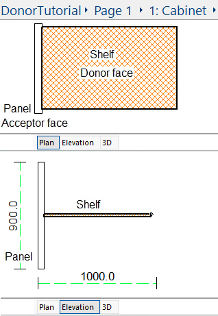 Consider the following example: You have a cabinet with an adjustable shelf which needs holes drilled into the end panels to support it. It may be easier to give the holes to the shelf as a donor step and allow these holes to be donated to the end panels. In this particular case, the left face of the shelf will touch the right face of the panel, so we will set the donor face of the shelf to be the left face - Donor Machine Steps Tutorial.
Specifies the maximum gap between the donor section and the acceptor section. Consider the previous example. Unless the panel is within the set tolerance of the shelf, the holes will not be donated to it.
Specifies the maximum gap between a donor step and its accepting part. For example, if a groove is being cut as a Fill strategy (because it is too wide for a single pass) the rectangle has to be extended beyond the border by the radius of the tool. This means that the accepted machine step has gone off the edge of the accepting part and will not be drawn unless a "side tolerance" is specified.
Use this button to toggle it ON or OFF so that the values displayed in the grid are values for _iscustomshapecalc set to Yes or No.
Toggles whether or not the formulas shown in the Detail List should be displayed as the value they evaluate to or the formula calculating the value.
These buttons  control the list of details for the machine step. In order the buttons are:
This list of details defines different values required by this specific Step Type.
There are four columns - Desc (Name), X, Y and Z. Depending on the type of row some of these fields may not be present, which is represented by the box being greyed out .
All values in this table can be referred to in formulas using the form rowname.X, rowname.Y or rowname.Z. For example CutSize.X would give the value 1311mm in the image above.
The first 6 rows (highlighted in pink) are always present and are provided for easy reference with other formulas. They cannot be modified here, and represent the following facts from the cabinet:
The type of machine step being done. This can be any of the following: