CabMasterPro User Guide
The Map tab area is where the user can link layers to strategies.
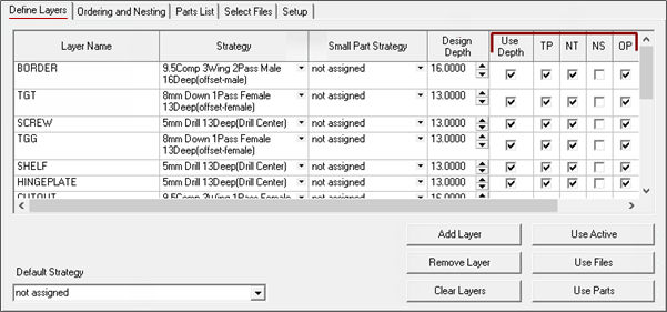
In previous versions this was called the Define Layers tab.
For quick links to more information, click on  the relevant area or another tab on the following image.
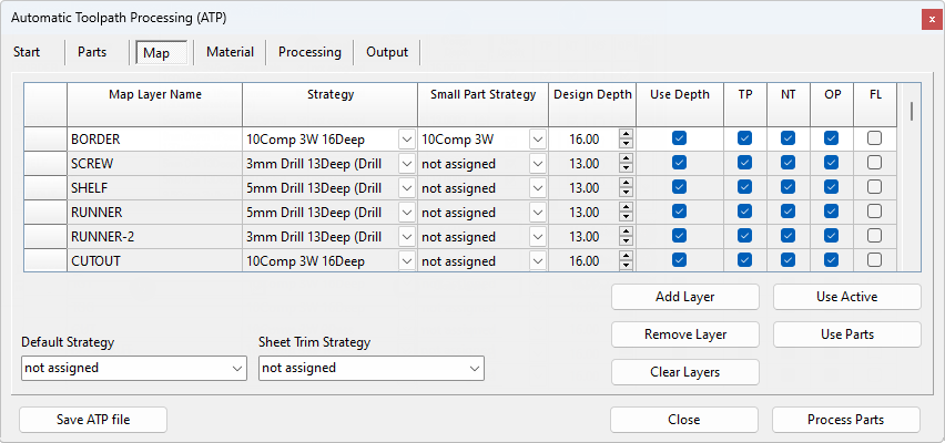
The Map Layer Name column contains a list of layers that may correspond to the layers included in the DXF files of the jobs to be processed. These layers are a collection of drill holes, rebates, routes, and other various shapes, that when combined with Strategies, will create the toolpaths that are applied to the parts on the nest.
The Layers can be identified in CabMaster Software™. In this example, the Layer name here is Hinge_35mm - click on the image to see how.
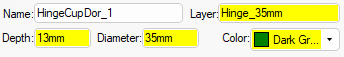
Layer name here is Hinge_35mm - Click to Expand
The Strategy and Small Part Strategy columns define which toolpath will be applied to that particular layer.
The Small Part Strategy will be used for any parts that have a surface area that is less than the threshold defined in the EzyNest Miscellaneous Settings.
This refers to the depth for which the selected Strategy was configured.
When Strategy Templates are created, the strategy is created with a specific depth. If a routing offset depth is set to a depth of 16mm, then this is the depth at which toolpaths will be created when this strategy is applied. If this strategy is used to cut out material that is 16mm thick, then this works great. However, if you also want to use this same strategy to cut out material that is 18mm thick, there could be a problem. The Design Depth parameter helps solve this issue. In this case, you would set Design Depth to 16mm, and click on Use Depth to put a tick in the checkbox.
It is very important that the Design Depth matches the Strategy depth exactly.
For example, shown above, the BORDER Strategy is 16Deep. Therefore it is important that the Design Depth is 16.00 i.e. exactly the same. If the Strategy is 16.1 then the Design Depth would have to be 16.1 to match.
If the Use Depth is enabled (ticked), CabMaster will provide the information to stretch the strategy to the required depth. This means that you can use the 16mm Strategy to cut an 18mm BORDER if required, and CabMaster will automatically adjust for it.
 Watch the Video EzyNest Design Depth Explained.
When the DXF geometry is created by CabMaster, it is typically placed at the depth at which it is intended to cut.
Routes that are to be cut at 16mm are placed 16mm below zero in the vertical (Z) axis. If Design Depth is specified, and Use Depth is ticked, EzyNest uses the vertical position of the route to determine whether to automatically adjust the Strategy depth. In our example, if the route is at -16mm, then no changes are made, but if the route is at -18mm, then the strategy would be modified to have a depth of 18mm. This means that the same strategy could be assigned to layers that will import geometry at different depths. (See Tip box above)
This provides an option for creating toolpaths for the geometry on each layer. Most of the time this parameter should be ticked. There may be cases, however, where information on a particular layer should not get toolpaths, but it should be included in the processed files.
This tells the ATP that this layer should be included with the ‘part’ that is defined in the rest of the DXF file. When output from CabMaster is being processed, this parameter should always be ticked.
If this checkbox is ticked, the layer will be included with the part in the toolpath output. This should be ticked in almost all cases. There may be unique situations in which geometry information is included in the part files that should not be included in the output, although this is a rare occurrence.
This checkbox is used for 6th Face Machining
The Default Strategy provides an option for specifying a strategy to be applied in every case where a layer is included in the parts and that layer is not in the Layer Name list.
Other Recommendations
The recommended settings for this tab are as indicated below.
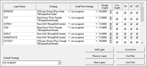
The BORDER layer should have an Offset-Male strategy applied, and the CUTOUT layer should have an Offset-Female strategy applied.
The Design Depth should be set for each layer and must match the depth of the strategy.
The checkboxes should be ticked for Use Depth, TP, NT and OP. Default Strategy should be set to “not assigned”.
All other options/settings not specified in the paragraph above can be set to your own preference.
This is an edit box and is also used for 6th face machining. It determines which strategy is used to trim the sheet to the correct size.
Adds a new blank layer to the list of layers. If you add a new layer, it will be default have “not assigned” for the Strategy and Small Part Strategy options, 0.0000 for the Design Depth, ticks in the checkboxes for Use Depth, TP, NT and OP.
This removes the selected layer from the list of layers.
Removes all items from the layers list.
This option is not required for use with CabMaster Software™ products, and so will not be covered in this document.
This takes the DXF files imported on the Parts tab (or AllMasterSoftware if using EnRoute), identifies any layers that are missing from the current layers list and adds those layers to the bottom of the list.