CabMasterPro User Guide
Separate cabinet Sections combine to form an entire cupboard. A cabinet can contain as few as one section or as many as are required. For example, a sink "cabinet" would consist of only a single thin horizontal section, with an appropriate bitmap applied to its top surface. On the other hand, a complex cabinet may have multiple drawers and shelves, which can consist of a few dozen sections.
A section is a simple box until you tell it what shape and size it has to be. Without recesses or overhangs applied, sections default to being the same size as the nominal sizes of their container.
The Nominal Width, Depth, and Height of a cabinet provide overall sizes that all the sections of the cabinet can reference. These nominal dimensions are designed so that you can make every section in the cabinet relative to them. If it is ever necessary to re-size a cabinet, you can simply change the nominal size values, and all the other sections will adjust themselves accordingly. This is much easier than altering the dimensions of each section individually. In a properly constructed cabinet, nearly everything should refer back to the nominal sizes, so that nothing requires editing manually when you re-size the cabinet.
Each section in a cabinet has to be contained within another section. By default, the container of a section is simply the cabinet itself. The cabinet is not an actual section; you can think of it as an imaginary box whose size you set through the Nominal Height, Width, and Depth variables. Instead of having the whole cabinet as its container, it is also possible to have a section contained within another section. The usefulness of sections within sections, or "nested" sections.
When you first create a new section, before any overhangs, recesses or offsets have been entered, it will always have exactly the same dimensions as its container. The section inherits the dimensions of its container, and those dimensions actually become the nominal size of the section.
For example, if you create a section called Top_drawer, it will have the whole cabinet as its container, and so will have a height equal to the Nominal Height, a width of Nominal Width, and a depth of Nominal Depth. If you now change the container of Top_drawer to a section called Carcass (which we assume is already built), the size of the drawer will change to be the same as the Carcass section. From this point you would alter the sizes so Top_drawer actually resembles a drawer.
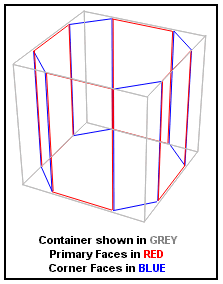
Every section has six primary faces, initially of zero thickness, that you can control independently of each other. Individual faces can be turned on by "sealing" them. You do this by checking the Sealed checkbox for the appropriate face, on the Faces page.
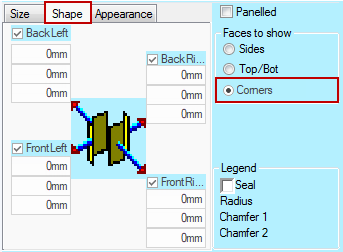 As well as the six primary faces, each section has four corner faces, sometimes called angled faces. You access these by turning on the "Faces to Show - Corners" radio button on the Faces page which will allow you to edit the four corner faces.
If all six primary faces of a section are sealed, then you will have a section that appears to be solid, but in fact is hollow. It is most important to create some sections in this way.
For example, let us consider a Benchtop. Every Floor Cabinet has a Benchtop section. As you add various Floor Cabinets next to each other in the formulation of a design, you want the various Benchtop Sections from the individual Cabinets to appear as one single piece. This is after all how it actually is. If however, we were to construct the Benchtop Section as a solid piece on top of every Cabinet, it would appear that way in the 3D view (i.e. you would see a line in the Benchtop at every Cabinet division). You can avoid this by constructing "hollow" Benchtop sections where the left and right faces are unsealed. In this way floor cabinets are effectively expecting you to place another Floor Cabinet next to them. This is the case most of the time, with the notable exception of the last cabinet in the run, in which case the designer simply seals the exposed end effectively closing the benchtop "tube".
The other option is to construct sections as Panels. To do this, the user simply seals the appropriate face(s) and applies a thickness to them. Thickness values must always be positive, otherwise the sections will be inside out, which does not make for particularly attractive 3D images. Positive thickness values always applies thickness towards the centre of the cabinet. Marking sections as Panelled is a more simplified approach than building panels out of individual sections. For example, it is possible to define a simplistic carcass from one section. In practice, this method would only be acceptable if all you wanted to achieve was 3D pictures approximating the finished article. For best results, limit multiple solid faces per section to situations that would lend themselves to "marking out in pairs".