In This Topic
The nesting, application of toolpaths, production of labels and output to the flatbed are carried out using
However, you to can Generate Nests directly in , without the need for accessing the ATP, Preferences and Driver Selection options in , which will run silently in the background to generate machining output files. Simply use the CNC Config available in .
Whether you use ™ or functionality to generate nests, both assumes that the configuration of Preferences, Tools, Machine Settings and Strategies has already been undertaken and an appropriate
Auto ToolPath template created.
Nesting in CabMasterPro
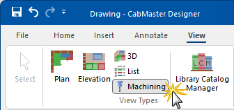
When you have completed your drawing/job...
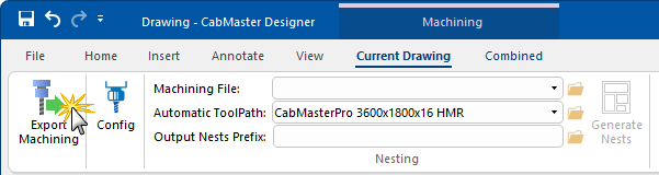
- Go to View > Machining to display the machining for the drawing;
Example
- Export Machining by using the command button
- This will generate one batch of part files () for each material used in the current drawing/job.
- See Machining View Current for more details.
Example
For a more efficient use of material, see
Machine View Combined where you can load several jobs and nest them together - as long as they all use the same material and tool set.
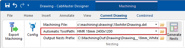
- This will provide drop list selections for...
- Machining File - allows you to select the machining file (DXT) to nest.
- Output Nests Prefix
 button allows you to browse to a folder (such as C:\MachiningOut\MyJob\ ) to be used to save generated CNC files and label files (per sheet).
- Automatic Toolpath - allows you to select the correct preconfigured file which defines the nesting parameters including the sheet size and other details - see Setup Sheet Size and Part Spacing.
- Set up the nesting process by using the Config
 command button which allows you to control the details of the current configuration without the need of opening , which will run silently in the background.
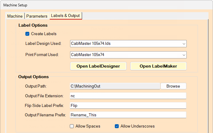
Labels & Output tab
- Ensure the Create Labels is ticked, if you need labels to be printed to identify each nested part.
- If labels are being produced, then the correct label design and stationery must be selected (normally remains the same).
- You can change the Output Path location (data file for the flatbed and label files) but in most situations, the output folder will remain the same.
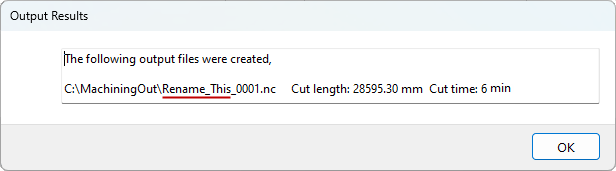
- Change the Output filename prefix from 'Rename_This' to a descriptive output file name.
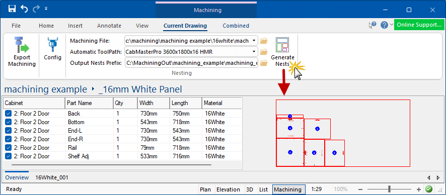
- Finally, click the Generate Nests command button which will generate files and display, as shown.
Using EzyNest or EnRoute
Export Machining [F8] your completed drawing/job - see Export DXF topic, then...
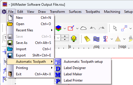
- Start
- Open the Automatic Toolpath setup dialog either from the File menu (see example) or clicking on ATP
 command button on the toolbar.
Example
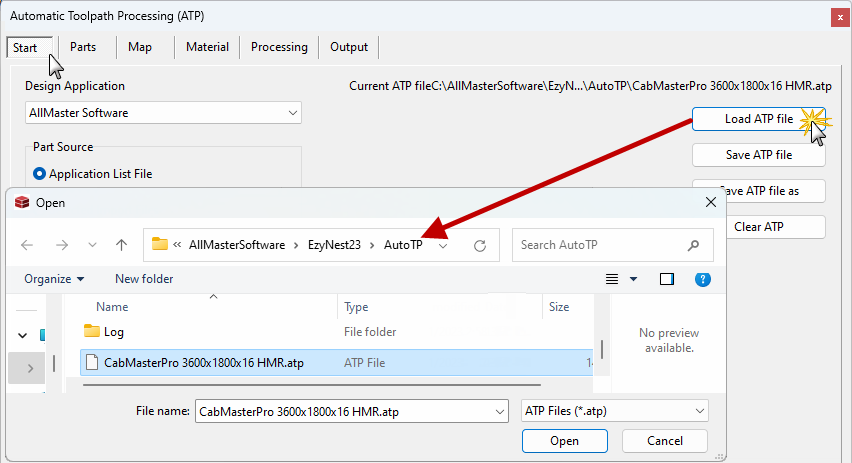
- From the Auto ToolPath (ATP) screen click on the Load ATP file button and select the correct file.
- If using , this is located on the Start tab, as per the example.
Example of Start tab
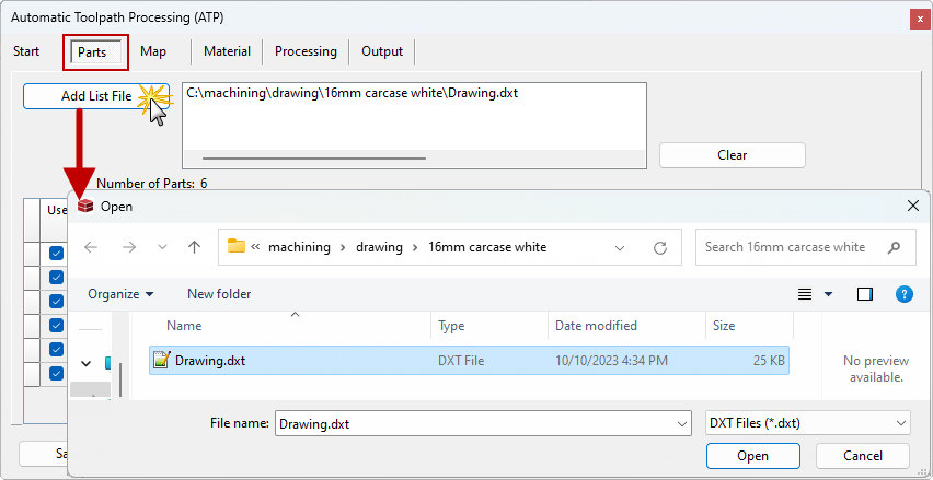
- Select the Parts tab and use the Add List File button to select the required Job file (the Job files have a DXT file extension).
- For a more efficient use of material, this step can be done repeatedly to load several jobs that need to be nested together.
- The proviso is that they all use the same material and tool set.
- To remove jobs from the list use the Clear button (Be aware that this will remove ALL the jobs from the list).
- The parts list will show all the individual doors/parts within each job. If required, certain details can be altered at this point e.g. Quantity.
Example of Parts tab
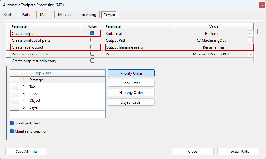
- Once all the required Jobs are in the list select the Output tab and ...
- Create Output - whether or not the data file for the flatbed is created.
- If you want to generate a printed copy of the nesting patterns, tick Create printout of parts
- Name the output file i.e. change the Output filename prefix.
- You can change the Output Path location (data file for the flatbed and label files) but in most situations, the output folder will remain the same.
- Ensure the Create Label Output is ticked, if you need labels to be printed to identify each nested part.
Example of Output tab
Older versions, all the above options are located on the Setup tab.
- When everything is correct, then click on the Process Parts button.
- This will apply the toolpaths, nest the doors, create the flatbed data and create the label files.
- Once this is complete a conformation message will appear. Click OK.
Example
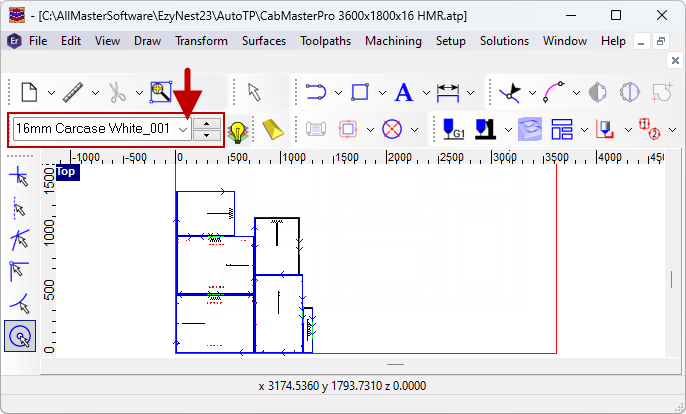
- The nesting, complete with toolpaths, will be shown.
See Also
Frequently Asked Questions
ATP